
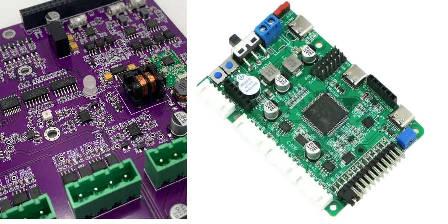
A welding robot PCB is a board inside the robot controller, servo system, welding power source, wire feeder, safety interface or process-sensing subsystem. It does not automatically carry the welding current: in most robotic cells, hundreds or thousands of amperes remain in the welding power stage, busbars, transformer and welding cables—not on the motion-control PCB.
Key Takeaways
- Define which PCBA is being quoted. Robot control, servo drive, weld-source interface, safety I/O and welding inverter boards have different voltages, risks and evidence.
- Separate welding-process current from control-board current. Heavy copper is justified only where the local board current and temperature-rise model require it.
- Validate every disturbance state, including arc ignition, short-circuit transfer, wire-feed transients, servo acceleration, contactor operation and emergency stop.
- Functional-safety claims belong to the complete architecture, diagnostics, software and validation. PCB fabrication quality alone cannot create a Performance Level or SIL.
- Control conductive dust, metal spatter, vibration, cable motion, thermal cycling and contamination through enclosure, placement, harness, cleanliness and coating decisions together.
- Put interface timing, isolation, fault response, test fixtures, traceability and change control in the RFQ so production evidence follows the real cell architecture.
Table of Contents
- What PCBs are used in a robotic welding cell?
- Where does the welding current actually flow?
- How should controller, power and safety domains be partitioned?
- How should welding-cell EMC be designed and tested?
- How should motion control and industrial communication be protected?
- What changes for a welding power-source PCB?
- How should environmental and mechanical reliability be validated?
- Which manufacturing evidence should be required?
- Common welding robot PCB failure modes
- Welding robot PCB RFQ checklist
- Frequently asked questions
What PCBs Are Used in a Robotic Welding Cell?
Industrial robot suppliers and welding-equipment manufacturers present the cell as an integrated set of subsystems. FANUC, for example, describes interfaces to the welding power source plus torch, wire-feeder and dress-pack integration. This architecture is more useful than treating the cell as one universal “welding robot PCB.”
| Cell subsystem | Typical PCBA functions | Main electrical risk | Acceptance owner |
|---|---|---|---|
| robot controller | path planning, real-time control, I/O and cell communication | timing, memory integrity, EMC and thermal loading | robot/control-system designer |
| servo drive | gate drive, current/voltage sensing, motor feedback and braking | high dv/dt, isolation, overcurrent and heat | drive designer and robot OEM |
| welding power source | rectification, inverter control, gate drive, current regulation and diagnostics | hazardous energy, switching fault and thermal stress | welding-power-source designer |
| weld interface board | command/status conversion, isolated analog/digital I/O or industrial Ethernet | ground-potential difference, surge and protocol state | cell integrator and equipment OEMs |
| wire-feeder controller | motor drive, encoder, gas/valve and consumable handling | stall, PWM noise, cable voltage drop and contamination | welding package designer |
| torch/seam sensor | touch sensing, arc sensing, through-arc or vision interface | common-mode voltage, arc interference and calibration | process-equipment designer |
| safety controller/I/O | guard, E-stop, enabling, safe motion and output monitoring | common-cause failure and diagnostic coverage | machinery safety architect |
| teaching pendant | HMI, enabling device, E-stop and communication | cable fatigue, drop, ESD and safety-channel integrity | robot OEM |
Arc welding, resistance spot welding, laser welding and plasma processes do not share the same electrical architecture. A resistance-welding gun may place a transformer and high-current secondary close to the robot. An arc-welding cell normally uses a separate controlled power source, wire feeder and torch circuit. Freeze the process and equipment partition before applying PCB rules.
Where Does the Welding Current Actually Flow?
The original equipment schematic should identify the complete welding loop. In an arc system, current flows from the welding power source through the electrode/torch, arc, workpiece and return cable. In resistance welding, very high secondary current flows through the transformer, buswork, gun arms and electrodes. Control PCBs issue commands and measure signals but ordinarily do not become the main welding conductor.
Use this current-path decision table:
| Current path | Appropriate construction | What must be verified |
|---|---|---|
| logic, encoder and communication | conventional controlled PCB traces and planes | signal/reference continuity, noise margin and protection |
| 24 V field I/O and valves | sized copper, connectors, fusing/current limiting and transient protection | simultaneous load, short circuit, hot plug and temperature rise |
| wire-feeder or auxiliary motor | driver stage, local bulk energy and controlled recirculation path | start/stall current, braking, cable drop and driver temperature |
| servo or weld inverter internal path | laminated busbar, power module, heavy copper or another qualified power interconnect as designed | fault energy, inductance, clearance, cooling and current sharing |
| external welding loop | welding cable, transformer/buswork, torch/gun and work return | cable size, connection, routing, duty cycle and process current |
A heavy-copper PCB may suit a local converter, motor drive or power-source subassembly, but “3–10 oz because welding uses high current” is not a valid specification. Calculate RMS/peak current, duty cycle, allowable temperature rise, copper geometry, vias, terminals and heat transfer. The weakest connector, neck-down or interface often controls the result.
How Should Controller, Power and Safety Domains Be Partitioned?
The controller architecture must prevent a power or process fault from silently corrupting motion or safety decisions.
- Keep inverter switch nodes, gate-drive loops and motor-current paths compact and away from encoder, analog and communication references.
- Define galvanic-isolation boundaries from working voltage, transient environment, grounding system and safety architecture. Do not add isolation without specifying insulation coordination and return paths.
- Use independent supervision for power-good, watchdog, clock, memory and communication faults according to the hazard analysis.
- Route user or field connectors through a controlled ESD/surge path before signals enter sensitive logic.
- Keep safety-related channels physically and logically controlled to the extent required by the selected architecture; document shared supplies, connectors, clocks and processors as potential common causes.
ISO 13849-1 or IEC 61508 methods may be used for safety-related control design, while ISO 10218 addresses industrial robot and robot-cell safety. A board can support diagnostic coverage, redundancy and safe outputs, but the claimed Performance Level or SIL depends on component reliability data, architecture, software, systematic capability, validation and the complete safety function.
The PCB manufacturer should receive unambiguous requirements—creepage/clearance, controlled impedance, copper, material, test points and acceptance criteria—not a request to “make the board safety rated.”
How Should Welding-Cell EMC Be Designed and Tested?
Welding cells combine an inverter, an arc or switched transformer, servo drives, long motor/encoder cables, contactors, valves and industrial networking. The correct EMC test is therefore state-based.
| Operating state | Disturbance mechanism | Possible PCBA symptom | Evidence to capture |
|---|---|---|---|
| arc ignition/re-ignition | fast common-mode and radiated transient | reset, false input, communication drop or sensor saturation | synchronized arc command, rail, reset, I/O and network log |
| short-circuit metal transfer | repetitive current step and magnetic field | analog error, encoder event or weld-data corruption | process current plus isolated-signal and error-counter capture |
| wire-feeder start/stall | motor inrush, PWM and cable drop | undervoltage, erratic feed or driver overtemperature | feeder current, local voltage, speed feedback and thermal data |
| robot acceleration/braking | servo current and DC-link dynamics | feedback errors or fieldbus jitter | servo state, DC-link/logic rails and network statistics |
| contactor/solenoid switching | inductive transient | output-channel damage or MCU disturbance | switching waveform, clamp path and recovery behavior |
| E-stop/safety trip | simultaneous de-energization and regenerative events | unsafe restart, latched fault or corrupted state | safety state sequence, discharge time and restart interlock |
| torch collision or cable motion | intermittent connector/shield contact | sporadic process and safety faults | powered continuity and shield-bond monitoring during motion |
Control noise at its source and return path. Use short power commutation loops, appropriate gate resistance/slew control, local decoupling, common-mode filtering where justified, and low-inductance chassis bonding. Terminate cable shields according to the system EMC plan; a long shield pigtail can defeat high-frequency bonding. Separate welding, motor, encoder, network and safety cables using the equipment supplier's routing rules.
IEC 60974-10 addresses EMC for arc-welding equipment. IEC 61800-3 applies to power drive systems, while IEC 61000-6-2 and IEC 61000-6-4 provide generic industrial immunity/emissions requirements when their scopes apply. The cell compliance plan must resolve which product-family standard takes precedence.
Pre-compliance probing is valuable, but emissions and immunity must be evaluated in representative cable, enclosure, load and grounding configurations. A clean bench test of the bare controller cannot reproduce arc-current return paths or the installed cable plant.
How Should Motion Control and Industrial Communication Be Protected?
Robot path accuracy is a system result involving mechanics, encoders, servo tuning, software, calibration, fixtures and welding-process behavior. A PCB should preserve timing and measurement integrity, but it cannot promise “micron-level welding precision” by itself.
For encoder and feedback inputs, define electrical standard, cable, termination, common-mode range, isolation, filtering, latency and fault detection. Filtering must reject interference without adding unacceptable control delay. For analog weld commands or feedback, specify scaling, accuracy, bandwidth, isolation and behavior during open/short conditions.
EtherCAT, PROFINET, EtherNet/IP and other industrial networks require the selected PHY, magnetics, connector, topology, cable and protocol stack to be implemented as a system. Controlled impedance and pair symmetry matter, but deterministic performance also depends on firmware, switches and network configuration. Safety protocols such as FSoE or PROFIsafe require an approved safety implementation and validation; placing ordinary Ethernet hardware on a PCB does not create a safety network.
Use a multilayer PCB where routing density, reference continuity, isolation and power distribution justify it. Maintain return paths through connector and layer transitions, and keep the industrial Ethernet launch away from inverter and motor-switching regions.
What Changes for a Welding Power-Source PCB?
When the quoted assembly belongs inside the welding inverter, the design moves into a high-energy power-electronics domain. The power stage may include rectification, a DC link, IGBT or SiC switching, transformer/inductor structures, output rectification and fast current control.
The release package should define:
- working/peak voltage, pollution environment, altitude and insulation coordination;
- semiconductor, gate-driver supply and isolation ratings;
- turn-on/off behavior, dead time, desaturation or overcurrent response and short-circuit energy;
- commutation-loop inductance, busbar/module interface and snubber/clamp design;
- current-sensor range, bandwidth, accuracy, isolation and saturation behavior;
- cooling interface, airflow/liquid cooling, thermal impedance and duty cycle;
- safe discharge, interlock and stored-energy service requirements.
Thermal vias and copper spreading help only when connected to a quantified heat-flow path. High-Tg laminate increases glass-transition margin but does not lower semiconductor junction temperature. Surface finish, copper weight and board thickness must follow assembly, current, thermal and reliability requirements rather than a universal “industrial” recipe.
How Should Environmental and Mechanical Reliability Be Validated?
Welding shops may expose electronics to conductive metal dust, oil mist, humidity, temperature cycling, vibration and cable motion. Put the controller outside the highest-contamination region where possible and control enclosure ingress, pressure/airflow, filtration and maintenance.
Conformal coating can reduce moisture and contamination risk, but only after ionic cleanliness is controlled. Specify coating material, thickness, cure, adhesion, coverage, keep-outs and inspection. Coating cannot repair poor creepage spacing, seal an enclosure or safely encapsulate trapped conductive debris.
Vibration qualification must reproduce the board's real mount, connectors, cable mass and component orientation. Through-hole termination is not automatically stronger than SMT; high-mass components and connectors need suitable support, retention and strain relief. Use through-hole assembly where the selected component and mechanical design require it, then verify the solder joint and hardware together.
| Exposure | Design control | Validation evidence |
|---|---|---|
| cabinet temperature and thermal cycling | derated components, measured airflow and controlled heat paths | multi-point temperature logs and powered cycling |
| conductive dust/metal particles | enclosure/filtration, spacing, cleanliness and coating if justified | contamination inspection and environmental test |
| robot/cable vibration | board support, connector locks, cable clamps and mass control | powered vibration with continuity/error logging |
| humidity/condensation | enclosure strategy, coating and corrosion-compatible materials | damp-heat/condensation plan and insulation checks |
| maintenance/replacement | keyed connectors, diagnostics, serialized assemblies and safe service state | replacement procedure and regression test |
Which Manufacturing Evidence Should Be Required?
| Control | Evidence | Why it matters |
|---|---|---|
| bare-board construction | stackup, copper, material lot, electrical test and impedance report where required | preserves current, insulation and signal assumptions |
| power/isolated spacing | finished geometry and inspection/microsection as specified | verifies modeled and safety-critical separation |
| solder process | profile, paste/flux, selective/wave parameters and repair record | controls voiding, wetting and thermal damage |
| hidden/critical joints | AOI and X-ray where package/joint geometry requires it | detects defects not visible from the surface |
| cleanliness/coating | ionic-cleanliness method/limit, coating material, cure and coverage inspection | prevents contamination from being sealed beneath coating |
| programming/calibration | firmware checksum, parameter set, identity and calibration record | prevents correct hardware shipping with wrong control data |
| functional test | isolated I/O, loads, feedback, faults, communication and recovery limits | proves interfaces and diagnostic behavior |
| traceability/change control | PCB, BOM, component lots, firmware, process and test fixture revision | makes long-life industrial failures diagnosable |
Functional testing should use safe load simulators for routine production and defined correlation units for representative motors, encoders, valves, networks or weld interfaces. “100% FCT” has no meaning unless the stimulus, limits, coverage and stored result are specified.
Common Welding Robot PCB Failure Modes
| Symptom | Likely causes | Discrimination check |
|---|---|---|
| controller resets only at arc start | common-mode transient, poor chassis bond, rail dip or reset injection | synchronized arc/rail/reset capture and bonding review |
| intermittent encoder alarm during motion | cable/shield damage, connector fretting, common-mode range or receiver margin | move-axis continuity plus differential/common-mode measurement |
| wire feed becomes unstable under load | cable drop, driver current limit, encoder noise or mechanical drag | motor current, local voltage and speed error correlation |
| safety trip will not reset | inconsistent channel state, contactor feedback, discharge delay or communication fault | safety sequence/event log against circuit timing |
| power device fails at weld initiation | gate-loop inductance, desaturation delay, overvoltage or cooling issue | double-pulse/fault capture and failed-unit physical analysis |
| field failures after coating | trapped contamination, missed keep-out, cure issue or connector wicking | cleanliness and coating cross-section/coverage review |
| failures follow one replacement lot | substituted part, solder/process drift or wrong firmware | serialized BOM/process/firmware traceability |
Welding Robot PCB RFQ Checklist
System and safety scope
- welding process, robot/weld-source/wire-feeder models and target markets;
- PCBA role, interface boundaries, operating modes and fault-energy sources;
- hazard analysis, safety functions, required PL/SIL architecture and validation owner;
- applicable robot, machinery, welding, drive, EMC and environmental standards.
Electrical and mechanical package
- schematic, BOM/AVL, Gerber/ODB++ or IPC-2581, drill, stackup and controlled drawings;
- voltage/current/duty-cycle table, isolation, creepage/clearance and transient requirements;
- fieldbus, encoder, analog, digital I/O, connector, cable and shield definitions;
- enclosure, airflow/cooling, mounting, cable loads, vibration and contamination conditions.
Manufacturing and validation
- soldering, press-fit/through-hole, coating, cleanliness and rework requirements;
- programming, secure data, calibration, parameter and firmware-release package;
- AOI, X-ray, ICT/flying probe and functional-test coverage with fixtures and limits;
- arc/disturbance-state EMC plan, environmental tests, fault injection and correlation units;
- serialization, raw-data retention, component lifecycle, approved substitutions and PCN rules.
HILPCB can review the released fabrication and assembly package, current paths, isolation geometry, connector mechanics, test access and panelization before quoting SMT assembly or turnkey PCB assembly. Robot accuracy, weld procedure qualification, functional safety, cell EMC and complete-system compliance remain with the designated OEM/integrator unless explicitly included through approved requirements and test assets.
Reference Standards and Specifications
- ISO 10218-1 — International Organization for Standardization
- ISO 10218-2 — International Organization for Standardization
- ISO 13849-1 — International Organization for Standardization
- ISO 13849-2 — International Organization for Standardization
- ISO 17662 — International Organization for Standardization
- IEC 60204-1 — International Electrotechnical Commission
- IEC 60974-1 — International Electrotechnical Commission
- IEC 60974-10 — International Electrotechnical Commission
- IEC 61508 series — International Electrotechnical Commission
- IEC 61800-3 — International Electrotechnical Commission
- IEC 61000-6-2 — International Electrotechnical Commission
- IEC 61000-6-4 — International Electrotechnical Commission
- IEC 60068-2-6 — International Electrotechnical Commission
- IEC 60068-2-27 — International Electrotechnical Commission
- IPC-6012 — IPC
- IPC J-STD-001 — IPC
- IPC-A-610 — IPC
- IPC-CC-830 — IPC
Use the revisions, safety category/performance target and regional requirements approved for the released machine.
Frequently Asked Questions
Does a welding robot control PCB carry the welding current?
Usually no. The main welding current flows through the welding power source, transformer or output stage, welding cables, torch/gun, workpiece and return. Control boards carry commands, feedback and auxiliary loads unless they are explicitly part of the power stage.
Does every welding robot PCB need heavy copper?
No. Heavy copper is selected from the local current, duty cycle, temperature rise and fabrication geometry. Logic and communication boards may use standard copper, while a motor or inverter subassembly may require heavier conductors or a busbar.
Can conformal coating protect the board from welding dust?
It can reduce risk after the board is properly cleaned, but it is not a substitute for enclosure, filtration, spacing and maintenance. Conductive particles trapped under coating can still cause leakage or corrosion.
Which EMC event is most important to test?
There is no single event. Test arc ignition and transfer states, servo acceleration/braking, wire-feeder start/stall, inductive load switching, E-stop and cable motion because each couples differently.
Can a PCB supplier certify the robot's Performance Level or SIL?
Not from fabrication alone. PL or SIL applies to defined safety functions and depends on architecture, component data, diagnostics, software, common-cause controls and validation of the complete system.
What should a production functional test include?
Verify rails, isolated and non-isolated I/O, communication, feedback channels, outputs, watchdogs, faults, programming and recovery. Use safe load simulators with approved correlation to representative equipment.
What data is needed for a welding robot PCB quote?
Provide the complete PCB/PCBA package, subsystem role, voltage/current states, interfaces, isolation, environment, standards, firmware/calibration, test fixtures, quantities, traceability and change-control requirements.
Validate the PCBA Inside the Real Welding Cell
Reliable robotic welding electronics begin with correct boundaries: the weld source controls process energy, the robot controls motion, safety functions control hazardous states and each interface preserves timing and isolation under real disturbances. Make those boundaries explicit, then require manufacturing and system-level evidence that remains traceable through every hardware, firmware and process change.