
For a through-hole connector pin, press-fit terminal, or mechanical mounting fastener, the only diameter that matters on the assembly line is the Finished Hole Size (FHS)—the clear internal opening remaining after fabrication is complete. The Drill Size (Ddrill) is an upstream manufacturing tool choice that the PCB fabricator selects to account for laminate resin movement, electroless copper seed, electrolytic barrel copper plating, and final surface finish.
When a designer exports an Excellon drill file without stating whether the numbers represent finished hole diameters or raw drill tool diameters—or applies a generic +0.10 mm plating offset to a compliant press-fit connector—either the fabricator over-compensates twice (producing oversized holes with weak solder fillets) or under-compensates (producing tight holes that bind component pins on the assembly line).
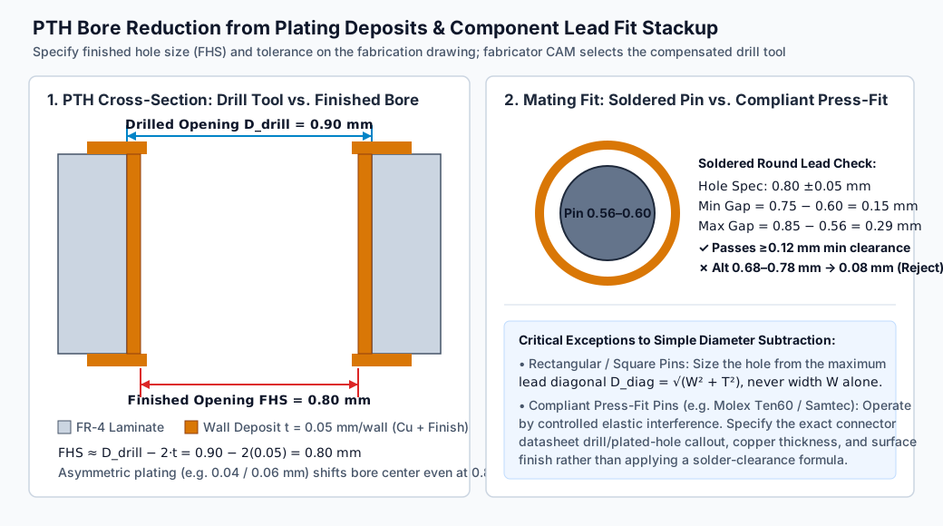
1. From Drilled Bore to Finished Opening: The PTH Wall Stackup
When a plated through-hole (PTH) is fabricated, the mechanical drill bit cuts an initial bore of diameter Ddrill through the copper-clad laminate. Subsequent wet-chemical and electroplating steps build metallic layers inward from the hole wall, reducing the clear opening by twice the total wall deposit thickness (2t):
As documented in Molex's Ten60 Power Product Specification PS-46436-100 (Revision E8, Section 7.1) and published fabricator galvanic guidance, different fabricators and board constructions require different drill tool compensations to hit the exact same finished hole size:
| Wall Layer / Process Factor | Typical Per-Wall Contribution | Why a Single "Universal Drill Offset" Fails Across Suppliers |
|---|---|---|
| Electroless Copper + Electrolytic Barrel Copper | 20--35 μm per wall (0.04--0.07 mm on diameter) | IPC-6012 Class 3, heavy-copper builds, or high-aspect-ratio boards require thicker barrel plating than standard Class 2 prototypes |
| Surface Finish Deposit | ENIG /OSP / Imm. Ag: <1--5 μm per wall; HASL: 10--40+ μm uneven meniscus |
Hot Air Solder Leveling (HASL) coats hole walls with a thicker, less uniform solder meniscus than planar chemical finishes like ENIG |
| Laminate Elastic Recovery (Hole Shrinkage) | Material- and drill-speed dependent (10--30 μm) | FR-4, high-Tg epoxy, and PTFE/ceramic laminates relax differently after the carbide drill bit exits the bore |
| Plating Current Distribution ("Dog-Boning") | Thicker plating at hole knee/entrance than at barrel center | High-aspect-ratio holes plate faster at the top/bottom openings than at mid-depth, creating a waisted bore profile |
Worked Deposit Geometry: Concentric vs. Asymmetric Wall Plating
In an idealized concentric model (plating-geometry-example.csv), if CAM selects a 0.90 mm drill tool and the process deposits a uniform t = 0.05 mm (50 μm) total layer on each wall, the finished hole diameter is:
However, if local plating distribution or drill runout deposits 0.04 mm on the left wall and 0.06 mm on the right wall, a caliper or pin gauge still reads 0.90 - (0.04 + 0.06) = 0.80 mm, yet the finished bore centerline has shifted laterally, and axial hourglassing between the hole knee and center can still bind a tight-fitting pin. This is why the designer should specify the required Finished Hole Size and tolerance (DFHS ± tol), leaving drill bit selection to the fabricator's qualified CAM compensation tables.
2. Sizing Soldered Through-Holes: Round Pins vs. Rectangular Leads
For wave-soldered, selective-soldered, or hand-soldered through-hole components, the finished hole must be large enough for automated/manual pin insertion across worst-case lead and hole tolerances, yet narrow enough for capillary action to draw molten solder up to the top-side land (typically 0.15--0.40 mm diametral clearance depending on board thickness and soldering method).
Case A: Round Component Lead Tolerance Stackup
Always compute minimum and maximum diametral clearance from the extreme limit dimensions, never from nominal values alone:
Suppose a round component lead has a specified diameter of 0.58 ± 0.02 mm (0.56--0.60 mm) and your assembly process requires at least 0.12 mm minimum diametral clearance for reliable insertion and solder fill (fit-tolerance-example.csv):
| Candidate Hole Specification | Finished Hole Range (DFHS) | Min Diametral Clearance (DFHS,min - 0.60) | Max Diametral Clearance (DFHS,max - 0.56) | Engineering Verdict |
|---|---|---|---|---|
Candidate 1 (Baseline): 0.80 ± 0.05 mm |
0.75--0.85 mm | 0.15 mm (0.75 - 0.60) | 0.29 mm (0.85 - 0.56) | PASS — Exceeds 0.12 mm minimum by +0.03 mm while keeping max gap ≤ 0.30 mm |
Candidate 2 (Tighter Alternate): 0.73 ± 0.05 mm |
0.68--0.78 mm | 0.08 mm (0.68 - 0.60) | 0.22 mm (0.78 - 0.56) | REJECT — Nominal 0.73 - 0.58 = 0.15 mm looks fine, but worst-case drops to 0.08 mm |
Note that this calculation covers single-pin diametral size only. On a multi-pin header or shrouded connector, positional true-position tolerance (GD&T \varnothing t) across the pin array and lead-tip true position also consume insertion clearance.
Case B: Rectangular and Square Pins (The Diagonal Rule)
A classic layout mistake is sizing a PTH from the flat width (W) of a square or rectangular header pin. A square 0.64 × 0.64 mm (0.025 in) header post touches the circular hole wall at its four corners, not its flat faces. Always calculate the maximum pin diameter from the maximum cross-sectional diagonal including lead tolerances:
For a 0.64 ± 0.02 mm square pin (W\max = T\max = 0.66 mm), the corner diagonal is √0.662 + 0.662 = 0.933 mm—meaning a 0.80 mm finished hole that easily accepts a 0.60 mm round lead will physically jam on a 0.64 mm square post.
3. Why Press-Fit (Compliant-Pin) Holes Cannot Use Solder-Clearance Math
Compliant press-fit pins (such as eye-of-the-needle or C-section terminals used in high-current power modules, automotive ECUs, and telecom backplanes) form a gas-tight cold weld through controlled radial interference between the elastic pin zone and the plated hole barrel. Applying a positive solder-clearance formula to a press-fit pin results in zero retention force and immediate electrical open failure.
As detailed in Samtec's Compliant Pin Termination Specification and Molex's Ten60 Power Specification PS-46436-100, a press-fit hole specification must lock four interdependent parameters directly from the connector manufacturer's print:
- Exact Reference Drill and Finished Hole Tolerance: Press-fit PTH tolerances are typically much tighter than soldered PTHs (commonly ± 0.05 mm or +0.05/-0.025 mm on FHS, often paired with a mandated reference drill bit size such as 1.15 mm drill for a 1.00 ± 0.05 mm finished hole).
- Copper Plating and Surface Finish Window: Too little barrel copper risks tearing the barrel wall during pin insertion; too much copper or a thick, uneven HASL finish increases insertion force and shears tin slivers. Planar finishes (such as Immersion Tin, ENIG, or OSP as specified by the connector datasheet) are typically required.
- Bore Cylindricity Through the Compliant Engagement Zone: In thick backplanes, excessive "hourglassing" (barrel plating thicker at the surface than in the compliant engagement depth) alters radial contact pressure.
- Minimum Board Thickness and Support Tooling: Ensure the PCB stackup meets the connector's minimum engagement thickness and that annular rings on outer/inner layers are sized for the specified press-fit drill diameter.
4. Specifying Plated Slots, NPTH Mounting Holes, and Master Hole Tables
Ambiguity in fabrication packages occurs most often on non-circular slots and non-plated through-holes (NPTH). Our downloadable master hole worksheet (filled-hole-requirements.csv) illustrates how to document four distinct hole families—including explicit holds where engineering data is incomplete:
| Feature / Callout | Hole Type & Plating | Functional Interface | Finished Dimension & Tolerance | Positional / Datum Basis | Current Engineering Status |
|---|---|---|---|---|---|
H01 (J1) |
Round PTH (Plated) | Round soldered connector lead (0.56--0.60 mm) | \varnothing 0.80 ± 0.05 mm FHS | Referenced to Datum A/B (DEMO-MECH-B) |
Size Verified (0.15--0.29 mm gap); confirm positional tolerance |
H02 |
Round NPTH (Non-Plated) | Mechanical M3 fastener / locating boss | \varnothing 3.20 +0.10/-0.00 mm FHS | Assembly drawing DEMO-MECH-B controls true position |
HOLD — Confirm whether hole is loose clearance or precision locating datum |
S01 (J2) |
Plated Routed Slot | Flat power blade terminal | 1.20 ± 0.05 mm wide × 2.40 ± 0.10 mm long FHS | Slot centerline and orientation per DEMO-MECH-B |
HOLD — Exported drill/route file omitted plated status; regenerate G85/route data |
H03 (J3) |
Round Press-Fit PTH | Compliant press-fit connector | Per specific connector datasheet print | Connector datum and engagement depth | HOLD — Do not guess diameter; attach exact connector part number and print |
(All three worked CSV files: filled-hole-requirements.csv, fit-tolerance-example.csv, plating-geometry-example.csv, and notes.)
Critical Rules for Plated Slots (S01) and NPTHs (H02)
- Never represent a rectangular power blade slot as a single oversized round drill hit unless the padstack and solder paste volume are explicitly designed for a large circular hole; an oversized circle consumes excessive routing space and requires far more wave/selective solder to fill without blowholes. Export slots on a dedicated slot/route layer or Excellon slot command with explicit width, length, end radii, and PTH/NPTH designation.
- Separate PTH and NPTH Excellon files (or verify unambiguous tool headers): As noted in published drilled-hole guidelines, incoming drill diameters are interpreted as finished hole sizes unless specified otherwise, and merging plated and non-plated holes without clear tool flags forces an immediate CAM hold.
- Keep Backdrilling Separate: If high-speed connector PTHs require controlled-depth stub removal, specify the stub length and backdrill span separately using our backdrill PCB design guide.
5. Resolving Drawing-vs.-Drill File Conflicts and Submitting Your RFQ
When a fabrication drawing table calls out \varnothing 0.80 ± 0.05 mm Finished Hole Size for H01 while the exported drill.drl file lists 0.90 mm for the same tool code, CAM cannot guess whether 0.90 mm was an intentional +0.10 mm designer drill-compensation attempt or a revision mismatch. Resolve the conflict through a formal Engineering Query (EQ), update the master archive so both the drawing and drill header state the same Finished Hole Size (FHS) convention, and re-verify annular rings on all layers (see Gerber data preparation and EQ control).
When submitting your PCB manufacturing RFQ to HILPCB, include:
- Master Hole Table on the Fabrication Drawing: Listing every tool code, hole count, PTH vs. NPTH status, round vs. slot geometry, and Finished Hole Size (FHS) tolerance.
- Component Drawings for Fit-Critical & Press-Fit Holes: Attach the exact connector manufacturer specification (e.g., Molex, Samtec, TE) for any compliant press-fit or precision alignment hole.
- Via Protection & Plugging Callouts: Distinguish component PTHs (which must remain open and clear of solder mask encroachment) from interconnect vias that require tenting, resin plugging, or VIPPO copper fill.
HILPCB fabricates precision multilayer PCBs and HDI boards with mechanical drilling down to 0.15 mm, CNC-routed plated and non-plated slots, controlled-depth backdrilling, and tight press-fit PTH barrel tolerances verified by pin-gauge and metallographic microsection inspection. Upload your Gerber/ODB++ files and hole table when you request a quote for a complete CAM review.
Frequently Asked Questions
Should my Excellon drill file contain finished hole sizes or compensated drill bit sizes?
Always export Finished Hole Sizes (FHS) in your Excellon drill file and state "ALL DRILL SIZES ARE FINISHED HOLE SIZES (FHS)" in your fabrication drawing notes. Because every PCB factory uses different plating bath thicknesses, laminate scale factors, and surface-finish compensations, pre-adding a manual drill offset in CAD risks double-compensation or under-sized holes.
How much larger than the component lead should a standard soldered PTH finished hole be?
For standard round through-hole leads soldered by wave, selective, or hand soldering, designers commonly target a diametral clearance of 0.15 mm to 0.30 mm (6--12 mil) between the maximum pin diameter (or maximum diagonal for square/rectangular pins) and the nominal finished hole size, then verify that worst-case minimum hole minus maximum pin still leaves ≥ 0.10--0.12 mm clearance. Always check the component datasheet first.
Why does HASL surface finish require a different hole tolerance or drill compensation than ENIG?
Electroless Nickel Immersion Gold (ENIG) deposits a thin, uniform chemical layer (≈ 3--6 μm Ni plus <0.1 μm Au per wall), preserving a cylindrical bore. Hot Air Solder Leveling (HASL) dips the board in molten solder and clears holes with hot air knives, leaving a thicker, slightly barrel-shaped solder coating (10--40 μm) that narrows the effective finished opening and generally requires wider FHS tolerances (e.g., ± 0.08 mm vs. ± 0.05 mm for ENIG) or a larger starting drill bit.
Can I shrink a component hole diameter in CAM just to fix an inner-layer annular ring violation?
Never reduce a component PTH's finished hole diameter to gain annular ring margin without first recalculating the worst-case pin-to-hole clearance against the component's maximum lead diameter or diagonal. If the hole cannot be shrunk without binding the component lead, enlarge the pad (or add teardrops) and verify adjacent trace clearance instead.