
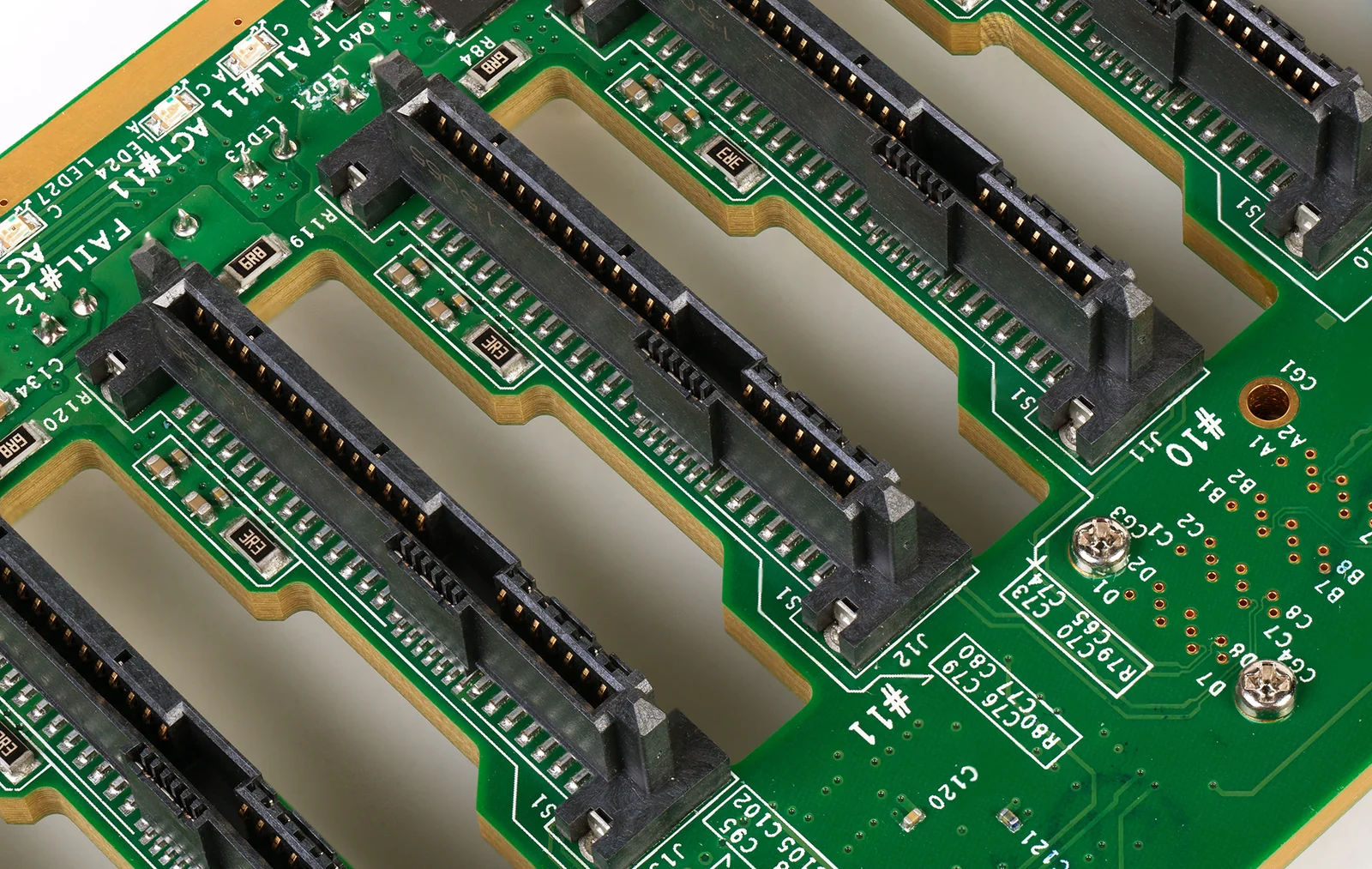
- What should usually be frozen first in AI server backplane PCB manufacturing is not layer count or board thickness by itself, but whether channel budget, thick-board stackup, backdrill window, press-fit hole zones, and board flatness can be repeated consistently across lots. On this kind of high-speed thick board, the real risk is not whether one board can be built, but whether every lot behaves similarly electrically and mechanically.
- A backplane cannot be treated as just a scaled-up conventional multilayer board. The public context around OIF 112G electrical interconnect and open server hardware in OCP both makes it clear that a high-speed backplane has to absorb connector effects, deep vias, in-board loss, and system-assembly boundaries at the same time.
- Low-loss material is not the only answer. On an AI backplane, what matters more is whether thick-board lamination, dielectric thickness, tolerance, glass style, and copper behavior can all be reproduced consistently.
- Backdrilling and deep-hole copper quality often decide first-lot yield together. If backdrill is treated only as a drawing note rather than a combined decision on residual stub target, verification method, and barrel-plating consistency, pilot production can become unstable quickly.
- The most valuable backplane validation is not that one board passes, but that multiple boards, multiple lots, and repeated press-fit assembly all behave consistently.
Quick Answer
The core of AI server backplane PCB manufacturing is not just combining a thick board with high-speed material. It is keeping budget allocation, lamination, tolerance, backdrilling, press-fit hole zones, and flatness aligned in real production. For high-speed switching backplanes and AI interconnect platforms, defining the process window before finalizing the drawing is usually the safer path.
Table of Contents
- What should engineers review first in AI server backplane PCB manufacturing?
- Summary table of key rules and parameters
- Why must backplane manufacturing begin by reasoning backward from channel budget?
- Why must low-loss material and thick-board stackup be judged together?
- Why should backdrill, deep-hole copper, and press-fit hole zones be reviewed together?
- Why is production release about lot consistency instead of one passing board?
- Next steps with HILPCB
- Frequently Asked Questions (FAQ)
- Public references
- Author and review information
What should engineers review first in AI server backplane PCB manufacturing?
Start with channel budget, thick-board stackup, backdrill and deep-hole structures, press-fit hole zones, and flatness validation.
This question does not mean "can the target board thickness be fabricated," and it does not mean "switching to a lower-loss material will solve the problem." OIF's public description of CEI 5.0 already sets the context around 112Gb/s electrical interconnect. OCP's open hardware platform context makes it equally clear that modern AI and server systems increasingly depend on high-density interconnect, modular structure, and high-speed backplanes. That means backplane manufacturing must deal simultaneously with connectors, deep vias, thick-board lamination, tolerance, and full-system assembly, rather than only with layer count.
Before design freeze, the five questions that are usually most useful are:
- How much budget is consumed separately by connectors, vias, the in-board trunk, and assembly variation?
- Do the thick-board material system and stackup match the target data rate and board-shape requirements?
- Do backdrill and deep-hole structures still sit inside a process window that can be held long term?
- Can press-fit connector hole zones and board flatness be reproduced consistently?
- Does validation cover multiple boards, multiple lots, and post-assembly condition?
If the platform itself combines high channel density, high layer count, and dense press-fit connector fields, it is usually better to bring the process boundaries of High-Speed PCB and Backplane PCB into the review early instead of trying to back-solve the manufacturing window after layout is finished.
Summary table of key rules and parameters
| Rule / Parameter | Recommended range or judgment method | Why it matters | How to verify | What happens if ignored |
|---|---|---|---|---|
| Budget decomposition | Split connector, via, in-board, and assembly variation contributions first | Backplane risk often comes from combined effects | Channel budget, local measurement | Material and backdrill strategy are judged on distorted assumptions |
| Thick-board stackup | Review material, dielectric thickness, copper balance, and lamination together | High-speed thick boards depend more on process stability | Datasheet, stackup review, coupon | Nominal impedance is right, but finished-board spread is large |
| Backdrill strategy | Define residual-stub target, drill depth, tolerance, and verification together | Backdrill is not just one drilling action | Cross-section, stub check, local comparison | First board works, lot production drifts |
| Deep-hole barrel copper | Review hole size, board thickness, and plating consistency up front | Directly affects high-speed and structural reliability | Microsection, barrel inspection | Via electrical life and mechanical life both suffer |
| Press-fit hole zone | Review hole position, tolerance, board thickness, and flatness together | Press-fit connectors are very sensitive to structural boundaries | First-article review, hole-zone check, board-shape recheck | Assembly becomes unstable and interface variation increases |
| Lot validation | Look at multiple boards and multiple lots, not just a single board | What a backplane delivers is repeatability | Multi-board comparison, lot record, FA | The golden sample is good, but production is unstable |
| Public context for high-speed backplanes | Direct implication for manufacturing |
|---|---|
| OIF 112G electrical interconnect | Budget cannot look only at long traces; local transitions are often more sensitive |
| OCP open server platforms | Dense connectors and modular structure amplify assembly boundaries |
| IPC rigid-board performance updates | Thick boards, deep vias, and structural validation depend more on coupons and cross-sections |
Why must backplane manufacturing begin by reasoning backward from channel budget?
Conclusion: Because the in-board segment on an AI server backplane is never the whole budget of the full link.
OIF's public context for 112Gb/s electrical interconnect already makes it clear that a high-speed backplane is a case where connectors, vias, in-board loss, and assembly variation all consume the same margin together, rather than a design that can be understood from differential-trace length alone. On AI server backplanes, if budget decomposition is done too late, the geometry and structure are often frozen first, and only afterward does the team discover that the material system, backdrill target, or press-fit connector window has already become too narrow.
What is worth freezing first includes:
- How much budget is consumed separately by the board interior, connectors, vias, and assembly variation
- Which critical channels really require more aggressive backdrill or a more stable material system
- Which local structures are short in length yet dominant in reflection and loss
- Whether the current structure is actually suitable for later press-fit and full-system assembly
For high channel-density projects, it is usually better to compare the channel and process window of High-Speed PCB and Backplane PCB early rather than chasing the source of the problem after pilot build.
Why must low-loss material and thick-board stackup be judged together?
Conclusion: Because the real risk on an AI backplane usually does not sit in the datasheet. It sits in the finished geometry after thick-board lamination.
On large, high-layer-count, thick backplanes, what really shapes the result is often not nominal Dk/Df, but whether dielectric thickness, copper roughness, resin flow, glass style, and lot consistency can all stay under control together. A lower-loss material system on paper still creates a fragile channel if the post-lamination geometry and consistency do not hold in production.
More useful early questions include:
- Does the current link really require a higher-grade material across the whole board?
- After thick-board lamination, do dielectric thickness and impedance geometry remain controllable?
- Will copper foil and glass weave amplify skew or local variation?
- Have supply stability and alternate-material risk already been brought into the volume-production plan?
If the project has already moved into large-size, high-layer-count construction, it is usually worth bringing the lamination and impedance windows of Multilayer PCB and High-Speed PCB into the same judgment instead of deciding only from one material parameter.
Why should backdrill, deep-hole copper, and press-fit hole zones be reviewed together?
Conclusion: Because on a thick high-speed backplane, these three structures often form the same risk package.
Long through-holes, thick-board geometry, and dense connector transitions amplify residual stubs, drill-depth variation, barrel-plating uniformity, hole position, and board flatness at the same time. If backdrill exists only as a process note on the drawing, without freezing stub target, verification method, deep-hole plating window, and press-fit hole-zone requirements together, the first production lot easily falls into "prototype usable, volume unstable."
The public update around IPC-6012F already shows that complex rigid boards depend more heavily on coupons, microsections, hole-position checks, and structural verification. For backplane projects, more valuable early actions include:
- Defining which networks must be backdrilled and which only need transition control
- Defining stub verification, cross-section strategy, and barrel-consistency checks
- Judging whether the current board-thickness-to-hole-size combination is already near the deep-hole boundary
- Writing press-fit hole position, tolerance, board thickness, and flatness into the same review cycle
If the project will enter the prototype stage next, it is usually better to move backdrill, cross-section, hole-zone, and flatness checks into PCB Prototype early. If press-fit assembly is already confirmed, SMT Assembly or downstream assembly review should be brought in early as well for boundary confirmation.
Why is production release about lot consistency instead of one passing board?
Conclusion: Because what an AI server backplane really has to deliver is stable connector, via, and assembly behavior in production quantity.
A truly reliable backplane is not the cleanest single prototype that works once, but one that keeps the same channel logic and assembly behavior across different board lots, connector lots, and assembly lots. If validation proves only that "this one board once succeeded," the design is still fragile.
A more practical pre-release checklist usually includes:
- Budget freeze. Are connector, via, in-board, and assembly variation contributions clearly separated?
- Material and stackup freeze. Are material grade, lamination window, impedance geometry, and copper balance jointly confirmed?
- Backdrill and barrel-copper freeze. Are the residual-stub target, cross-section strategy, and barrel-consistency checks clearly defined?
- Hole-zone and assembly freeze. Are press-fit hole position, tolerance, and flatness boundaries already written into manufacturing requirements?
- Validation-matrix freeze. Are coupon, cross-section, backdrill verification, assembly checks, and lot feedback all inside one matrix?
If the project is already approaching pilot production, it is usually better to organize these inputs into Quote / RFQ or front-loaded engineering instructions rather than using only a single-board bring-up result as the release basis.
Next steps with HILPCB
If you are currently moving an AI server backplane, high-speed switching backplane, or dense press-fit interconnect platform forward, the next step is usually to turn "the sample can be built" into "the platform can be delivered repeatedly."
- When the main issue is critical channel budget and connector zones, first use the High-Speed PCB and Backplane PCB paths to converge interface structure.
- When the project has already moved into thick-board, high-layer-count, and large-size structure, check the stackup and lamination boundaries of Multilayer PCB at the same time.
- When risk is concentrated in backdrill, deep vias, and press-fit hole zones, moving those checks into PCB Prototype exposes issues earlier.
- Once budget, material, backdrill, and assembly boundaries are all clear, organizing them into Quote / RFQ or the next assembly review makes the full boundary easier to explain in one pass.
Frequently Asked Questions (FAQ)
Does an AI server backplane always require ultra-low-loss material?
A: Not necessarily. The need for a higher-grade material depends on real channel length, the number of connector transitions, board thickness, and the process window, not on the material label alone.
If backdrill is included, is the via problem solved?
A: No. Backdrill is only part of via control. Residual stubs, drill-depth variation, barrel-plating uniformity, and verification method all have to be frozen together.
Why can assembly still fail easily when the backplane has few active devices?
A: Because connectors, press-fit hardware, and thick-board structures are highly sensitive to hole position, tolerance, flatness, and stress distribution, and those variables often show up before the traces themselves do in production.
What is most worth freezing before fabrication?
A: Prioritize channel budget, material and stackup, backdrill and residual-stub logic, press-fit hole-zone requirements, flatness boundaries, and the validation matrix.
What are the most valuable real manufacturing data points for a backplane?
A: Coupon data, cross-sections, backdrill verification, hole-position trend, board warp, and flatness records are more valuable than generic claims about "high-speed board capability."
Public references
OIF Releases Common Electrical I/O CEI 5.0 Implementation Agreement
Supports the article's explanation that in the public context of 112Gb/s electrical interconnect, a high-speed backplane must be understood as a combined structure of connectors, vias, and in-board channel behavior.Open Compute Project Projects
Supports the article's public background that open server and AI platforms continue to increase high-density interconnect, modular structure, and backplane complexity.IPC Releases IPC-6012F Qualification and Performance Specification for Rigid Printed Boards
Supports the article's statement that complex rigid boards depend more heavily on coupons, cross-sections, and structural verification.IPC Design Standards
Supports the article's public standards background that impedance, geometry, DFM, and manufacturing window should be reviewed together.
Author and review information
- Author: HILPCB High-Speed Backplane Content Team
- Technical review: PCB process, SI, and DFM engineering team
- Last updated: 2026-05-15