
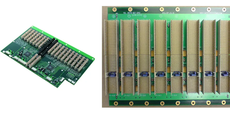
In the era of exponential growth in Artificial Intelligence (AI) and Machine Learning (ML), data centers are undergoing an unprecedented architectural revolution. At the core of this revolution is the AI server, and the foundation of its performance is a seemingly ordinary yet extremely complex electronic component—the AI server motherboard PCB. As a compliance and reliability engineer responsible for HALT/HASS, signal integrity testing, and boundary scan, I know full well that this backplane PCB is not only the physical carrier connecting the GPU, CPU, memory, and network modules, but also the "nerve center" determining whether the entire system can operate stably for long periods under 24/7 high loads.
The design and manufacturing of AI server backplanes have long transcended the field of traditional server PCBs. They need to carry up to several kilowatts of power, process PCIe 5.0/6.0 or even higher rate signals, and effectively dissipate heat within dense spaces. Any minute design flaw or manufacturing defect could lead to signal distortion, power collapse, or overheating crashes, resulting in catastrophic data processing interruptions. From the perspective of reliability engineering, this article will deeply analyze the core challenges and solutions of AI server backplane PCBs in aspects such as high-speed signal integrity, power distribution, thermal management, and design for testability, helping you navigate this advanced technology.
Why is the AI Server Backplane PCB the Nerve Center of the Data Deluge?
Traditional server motherboards usually integrate the CPU, memory, and I/O on a single board, whereas AI servers adopt a modular design to maximize parallel computing capabilities. Through a high-density, high-performance backplane, it connects multiple GPU accelerator modules (like NVIDIA's SXM or OAM), CPU modules, high-speed Network Interface Cards (NICs), and storage devices. This architecture makes the AI server motherboard PCB the communication backbone of the entire system.
Its core role is reflected in the following aspects:
- Ultra-High Bandwidth Interconnect: AI model training involves the frequent exchange of massive amounts of data among GPU clusters. The backplane PCB must provide ultra-low latency and ultra-high bandwidth physical links for GPU-to-GPU communication (like NVLink) and CPU-to-GPU communication (like PCIe). This demands excellent high-speed signal transmission capabilities from the PCB, representing a typical high-speed AI server motherboard PCB application scenario.
- Massive Power Distribution: The power consumption of a single AI accelerator can reach 700W or even over 1000W, and the total power consumption of a fully configured AI server can reach several kilowatts. The backplane PCB needs to precisely and stably distribute these massive currents to each computing module, placing extreme demands on the design of the Power Delivery Network (PDN).
- Complex System Topology: To achieve flexible expansion and upgrades, AI server backplanes support various complex connection topologies, such as All-to-All, Ring, or hybrid topologies. This results in extremely high routing density on the PCB, with the number of layers typically exceeding 20, making design and manufacturing highly difficult.
- Reliability and Serviceability: As core assets of data centers, AI servers demand extremely high operational reliability. The backplane design must consider long-term operational stability and the capability for rapid diagnosis and replacement when faults occur, which is critical throughout the product's entire lifecycle, especially during the NPI EVT/DVT/PVT (Engineering, Design, and Production Verification Testing of New Product Introduction) phases.
High-Speed Signal Integrity: Mastering the Design Challenges of PCIe 5.0/6.0
With the popularization of PCIe 5.0 (32 GT/s) and the arrival of PCIe 6.0 (64 GT/s), the signal rates on AI server backplanes have entered the Radio Frequency (RF) domain. At such rates, PCB traces are no longer simple "wires," but complex transmission line systems. As reliability engineers, ensuring Signal Integrity (SI) is the top priority of our work.
Key challenges include:
- Insertion Loss: The energy of high-speed signals attenuates during transmission, especially over long-distance backplane traces and across multiple connectors. We must choose Ultra-Low Loss or Extremely-Low Loss PCB materials, such as Megtron 6, Tachyon 100G, etc., to reduce the dissipation factor (Df) and conductor loss.
- Impedance Control: The impedance of differential pairs must be strictly controlled at 100Ω or 85Ω (within ±5%). Any impedance discontinuity, such as vias, connectors, or changes in trace width, will cause signal reflections, degrade the eye diagram, and increase the Bit Error Rate (BER). Precise impedance control is one of the core capabilities in high-speed PCB manufacturing.
- Crosstalk: In high-density routing, the electromagnetic fields between adjacent signal lines will interfere with each other. We suppress Far-End Crosstalk (FEXT) and Near-End Crosstalk (NEXT) by optimizing trace spacing, planning reasonable routing paths, and using ground shield layers.
- Timing & Jitter: Signal jitter compresses the horizontal opening of the eye diagram, affecting data sampling. From material selection to via design, every link must strive to minimize sources of jitter.
Throughout the NPI EVT/DVT/PVT process, we use simulation tools such as ANSYS HFSS and Keysight ADS to conduct extensive early-stage SI simulations and late-stage validations, ensuring the design meets specification requirements before entering manufacturing.
Comparison of PCB Loss Budget Requirements Across PCIe Generations
| PCIe Standard | Data Rate (GT/s) | Nyquist Frequency (GHz) | Total Channel Loss Budget (dB) | PCB Material Requirements |
|---|---|---|---|---|
| PCIe 4.0 | 16 | 8 | ~28 | Mid Loss / Low Loss |
| PCIe 5.0 | 32 | 16 | ~36 | Low Loss / Ultra-Low Loss |
| PCIe 6.0 | 64 (PAM4) | 16 | ~32 | Ultra-Low Loss / Extremely-Low Loss |
How Do Complex Stack-up and Via Technologies Affect Backplane Performance?
A high-performance AI server motherboard PCB typically has 20 to over 30 layers, and its stack-up design is the foundation of the entire project. A well-designed stack-up not only provides ample routing space but is also fundamental for controlling impedance, shielding crosstalk, and constructing a low-impedance power network.
Our stack-up design principles include:
- Symmetrical Structure: To prevent board bowing and warping during manufacturing, the stack-up design must remain symmetrical, which is particularly important for backplanes with massive dimensions.
- Reference Plane Integrity: Each high-speed signal layer must be adjacent to a solid Ground (GND) or Power (PWR) plane as its return path reference. Any split in the reference plane will lead to impedance discontinuities and severe EMI issues.
- Power/Ground Plane Pairing: Tightly coupling the power and ground layers can form a natural planar capacitor, providing a low-impedance path for high-frequency currents, which helps enhance Power Integrity (PI).
Vias are critical for connecting traces across different layers, but in high-speed signals, they also pose a major performance bottleneck. Traditional Through-hole Vias create unnecessary "stubs" that act like antennas radiating energy at high frequencies, causing severe reflections. To resolve this, we employ advanced via technologies:
- Back-drilling: After the PCB manufacturing is completed, the excess stubs of the vias are drilled out from the back of the board. This is a highly cost-effective method for improving signal integrity and is almost indispensable for PCIe 4.0 and higher rates.
- HDI (High Density Interconnect) Technology: Using laser-drilled Microvias, as well as Blind Vias and Buried Vias. This not only vastly increases routing density but also significantly shortens the signal path, reducing the parasitic inductance and capacitance of the vias. HilPCB PCB Factory (HILPCB) possesses extensive experience in HDI PCB manufacturing and can support complex design needs.
The Critical Role of Power Integrity (PDN) in High-Power AI Modules
If signal integrity is to ensure the "clear" transmission of data, then Power Integrity (PI) is to guarantee the "forceful" operation of the system. AI accelerators have an extremely high demand for transient current (di/dt), requiring massive currents in incredibly short durations. If the PDN design is poor, it will lead to voltage rail collapse, directly triggering system crashes.
Our PDN design strategy focuses on achieving ultra-low impedance across the entire path from the VRM (Voltage Regulator Module) to the GPU/CPU chips:
- Planar Capacitance: Using tightly coupled power and ground layers to construct a large-area planar capacitor, providing a low-impedance path for high-frequency noise.
- Decoupling Capacitors: Placing a large number of decoupling capacitors near the power pins of the chips. These capacitors act like miniature energy storage reservoirs, able to respond quickly when the chip requires instantaneous high current. The selection and placement of capacitors need to cover the entire frequency spectrum from low to high frequencies.
- VRM Layout and Copper Design: Placing the VRM as close to the load (GPU/CPU) as possible to shorten the current path. Employing thick and wide copper pours or heavy copper PCB technology to reduce Direct Current (DC) voltage drop and resistance loss.
A robust PDN design commands reliability requirements comparable to an automotive-grade AI server motherboard PCB, because any power fluctuation might lead to computational errors, which is unacceptable in critical applications such as scientific computing or financial modeling.
⚡ PDN Integrity: Power Delivery Network Design Matrix
Comprehensive Stability Control from DC IR-Drop to AC Impedance
Design Guideline: Reject rules of thumb. Calculate the full-frequency target impedance Ztarget based on the chip's transient current Δ I and allowable voltage ripple Δ V. Ensure the PDN impedance curve remains consistently below the target value within the chip's operating bandwidth to prevent systemic voltage drops.
Layout Strategy: Build a hierarchical energy storage system. Large-capacity capacitors (Bulk) handle low-frequency compensation, while small-capacity capacitors (Decoupling) manage high-frequency transient needs. Physical location dictates effectiveness: Small-sized capacitors like 01005/0201 must be placed right next to the chip pins to minimize Equivalent Series Inductance (ESL).
Engineering Essentials: The power/ground network should be equipped with a large number of vias. It is strictly forbidden for multiple decoupling capacitors to share the same via to prevent noise coupling caused by common path inductance. Adopt a symmetrical ground via layout to lower the loop inductance of the high-frequency return path.
Closed-Loop Validation: Perform DC IR-Drop and AC Impedance simulations before Tape-out. Use current density heatmaps to identify "narrow waists" or bottleneck areas in the power plane, eliminating local over-temperature risks and optimizing Plane Splitting.
For high-speed digital systems below 1V, HILPCB provides an Embedded Capacitance material technology solution, effectively and significantly reducing high-frequency impedance. Simultaneously, through high-precision Heavy Copper Layering technology, we ensure your DC power network features extremely low voltage drop loss.
Thermal Management: Cooling Down Multi-Kilowatt AI Servers
Heat is the number one killer of electronic system reliability. Inside a fully loaded AI server chassis, power consumption can reach 10-15kW, generating a heat flux density far exceeding that of traditional servers. Although the AI server motherboard PCB itself is not the primary heat source, it carries all the high-power devices and acts as a critical path for heat transfer.
Our thermal management strategy is systematic, and PCB design is a vital part of it:
- High Thermal Conductivity Materials: Selecting PCB substrates with a high glass transition temperature (Tg) and high thermal conductivity (Tc), such as High Tg FR-4 or more advanced ceramic-filled materials, ensuring the PCB maintains mechanical and electrical performance stability even at high temperatures.
- Optimized Copper Pour Layout: Laying out large areas of copper on both the surface and inner layers of the PCB, exploiting copper's excellent thermal conductivity to rapidly transfer heat from heat sources (like VRMs and the bottoms of chips) to heatsinks or the chassis.
- Thermal Vias: Arraying a massive number of thermal vias beneath heat-generating devices to conduct heat vertically from the layer where the device resides to the opposite side or inner thermal planes of the PCB, significantly reducing thermal resistance.
- Embedded Cooling Technologies: For areas with extreme power consumption, advanced technologies like Embedded Coins or Heat Pipes can be used to embed cooling structures directly within the PCB, providing the most efficient heat conduction paths.
Effective thermal management not only prevents devices from throttling or failing due to overheating but also substantially extends the operational lifespan of the entire system, forming the bedrock for achieving long-term reliability.
Reliability Validation in Manufacturing and Assembly: From NPI to Mass Production
A perfect design is nothing more than theoretical if it cannot be precisely manufactured. For a product as complex as an AI server motherboard PCB, interaction between design and manufacturing (DFM/DFA) is critical. At a specialized manufacturer like HILPCB, we get involved early in the project to provide DFM analysis, ensuring the design scheme not only meets performance requirements but also possesses high-yield mass manufacturability.
The entire product lifecycle follows a strict NPI EVT/DVT/PVT process:
- EVT (Engineering Verification Test): This phase primarily verifies basic functionalities and design concepts. Producing a small number of prototype boards, i.e., an AI server motherboard PCB low volume order, for electrical function validation, preliminary signal integrity measurements, and basic firmware debugging.
- DVT (Design Verification Test): This is the most comprehensive testing phase. We conduct complete signal integrity, power integrity, thermal performance, and EMC tests on the PCB. Simultaneously, HALT (Highly Accelerated Life Testing) is performed to quickly expose weak links in design and manufacturing by applying temperature and vibration stresses that far exceed specifications.
- PVT (Production Verification Test): This phase aims to verify the stability and yield rate of the mass production process. We will run small-batch pilot productions using the final production tooling and testing procedures, ensuring that every link from manufacturing to assembly is stable and reliable.
Through this series of rigorous validations, we ensure that every delivered high-speed AI server motherboard PCB can operate flawlessly on the customer's site for the long term.
🚀 AI Server Backplane: NPI Digital Introduction and Quality Engineering
System-Level Validation Flow for Multi-GPU Interconnects, High-Speed Cable Backplanes, and 10kW+ Power Architectures
Based on 224G routing planning, execute Full-wave SI/PI/Thermal co-simulation to define the specifications for Ultra-Low Loss substrate materials.
Engineering prototype validation. Focus on Power-up timing, interface logic, and the physical mating of the Orthogonal Connector to the backplane.
Comprehensive reliability testing. Introduce HALT (Highly Accelerated Life Testing) to verify signal eye diagram opening and gold finger wear under extreme vibration and high-heat environments.
Mass production process lock-in. Validate the back-drilling tolerance, lamination precision, and impedance CPK indicator stability of large-size backplanes with 20+ layers through Run@Rate.
Enter continuous delivery. Execute HASS (Highly Accelerated Stress Screening), ensuring the electrical quality consistency of every shipped backplane via Automated Test Equipment (ATE).
For high-aspect-ratio backplanes of 20 layers and above, we provide an ASL (Adaptive Scaling Logic) compensation algorithm during the NPI phase. By modeling data on inner-layer material shrinkage, we ensure a 30% improvement in via alignment accuracy in the high-frequency section, helping your AI project smoothly transition from prototype to SOP.
The Application of Boundary-Scan/JTAG in Complex Backplane Testing
As the pins of BGA (Ball Grid Array) packages become increasingly dense, traditional ICT (In-Circuit Testing) flying probes or bed-of-nails can no longer access the vast majority of solder joints. This poses a massive challenge to the quality validation of PCBA (Printed Circuit Board Assembly). In this scenario, Boundary-Scan/JTAG (IEEE 1149.1 standard) technology becomes especially important.
Boundary-Scan/JTAG is a test architecture built into many modern ICs (such as CPUs, FPGAs, ASICs). By adding a "boundary-scan cell" at each IC pin, all these cells are chained together in a scan chain. Through the JTAG Test Access Port (TAP), we can:
- Test Connectivity: Detect open circuits, short circuits, and solder joint defects between BGA pins without needing physical probes. This is essential for verifying the connection quality of thousands of pins between the backplane and the daughtercard connectors.
- In-System Programming: Perform in-system programming and configuration for devices like FPGAs, CPLDs, and flash memory, simplifying the production workflow.
- Functional Testing Assistance: During initial system power-up, JTAG is a powerful tool for board-level debugging and diagnostics, aiding engineers in quickly localizing hardware issues.
Integrating Boundary-Scan/JTAG testing is an indispensable step in the assembly testing of AI server backplanes. Not only can it cover testing blind spots unreachable by ICT, but it also dramatically improves testing efficiency and fault diagnosis accuracy. It is a key technical safeguard to ensure the quality of complex, high-density PCBAs.
How to Select the Right AI Server Backplane PCB Manufacturer?
Choosing an appropriate manufacturing partner is critical to the success of an AI server project. An outstanding manufacturer is more than just a build-to-print vendor; they should be a partner capable of providing deep technical support, securing supply chain stability, and ensuring the reliability of the final product.
When evaluating manufacturers, you should focus on the following core capabilities:
Technical Capabilities:
- High Layer Count and Large Size: The ability to stably produce PCBs with over 30 layers and dimensions exceeding 600mm x 800mm.
- Advanced Material Experience: Whether they possess extensive experience in handling high-speed materials like Megtron 6/7, Tachyon 100G, etc.
- Precision Manufacturing Tolerances: The capacity to achieve strict line width/spacing control (e.g., 3/3mil), precise impedance control (±5%), and highly accurate back-drilling depth control.
- Advanced Process Support: Whether they have advanced manufacturing capabilities such as HDI, embedded passive/active components, and heavy copper.
Quality and Reliability Systems:
- Certifications: Whether they have passed quality and environmental management system certifications like ISO 9001, ISO 14001, and IATF 16949. Even if it's not an automotive product, possessing manufacturing quality control standards akin to an automotive-grade AI server motherboard PCB signifies a commitment to high reliability.
- Testing Capabilities: Whether they are equipped with advanced AOI (Automated Optical Inspection), AVI (Automated Visual Inspection), and X-Ray inspection equipment, and possess the capability to support Boundary-Scan/JTAG testing.
- Reliability Laboratory: Whether they have the capacity to conduct environmental reliability tests such as thermal shock, temperature and humidity cycling, and vibration testing.
Services and Support:
- One-Stop Service: Whether they can provide turnkey assembly services spanning from PCB manufacturing to component procurement, SMT placement, and complete system assembly, thereby simplifying supply chain management.
- DFM/DFA Support: Whether they offer professional engineering support early in the project to help optimize the design, reduce costs, and improve manufacturability.
- Flexible Capacity: Whether they can support capacity requirements from rapid prototyping of AI server motherboard PCB low volume orders during the prototype phase to large-scale mass production.
HilPCB PCB Factory (HILPCB) focuses on manufacturing and assembly services for high-layer, high-density, and high-reliability PCBs. We have accumulated rich project experience in the high-speed AI server motherboard PCB sector and can provide you with one-stop solutions from design optimization to final delivery.
FAQ
Why is the AI server backplane PCB such a critical board in the system?
Because it is the interconnect backbone linking GPUs, CPUs, memory, NICs, and storage modules. Its quality directly affects bandwidth, power delivery, uptime, and serviceability across the whole server.
What makes PCIe 5.0 and PCIe 6.0 routing so difficult on AI server backplanes?
At those data rates, insertion loss, impedance discontinuities, crosstalk, and jitter all become major channel risks. That forces careful material selection, simulation, connector planning, and via optimization.
Why must power integrity and thermal design be treated together?
Multi-kilowatt AI systems create both heavy current demand and concentrated heat. A backplane that cannot maintain a low-impedance PDN and an effective cooling strategy will face voltage droop, hot spots, and stability problems.
Why is Boundary-Scan/JTAG still valuable on complex AI backplanes?
It helps test hidden interconnects around dense BGA devices, supports in-system programming, and speeds up hardware fault isolation. That makes it especially useful when ICT access is limited.
Conclusion
The AI server motherboard PCB is one of the most technology-intensive and challenging components in modern AI infrastructure. It fuses advanced technologies from multiple domains, including high-speed digital, RF, power electronics, and thermodynamics. As reliability engineers, we deeply understand that to successfully build a stable, high-performance AI server backplane, we must pursue the ultimate in every link of design, manufacturing, and testing.
From selecting the correct ultra-low loss materials to designing a robust PDN and efficient cooling solutions; from using back-drilling and HDI technology to optimize signal paths, to conducting stringent validation across all NPI EVT/DVT/PVT stages; and then to ensuring assembly quality through advanced means like Boundary-Scan/JTAG, every single decision directly impacts the performance and reliability of the final product.
Handling these challenges requires profound technical expertise and formidable manufacturing capabilities. Choosing an experienced and technologically leading partner like HILPCB will be key to helping you stay undefeated in the wave of AI. If you are developing the next generation of AI servers and are seeking a reliable PCB manufacturing and assembly partner, please contact us immediately. Our expert team is always ready to provide you with free DFM analysis and offer the most competitive quotation for your project.