
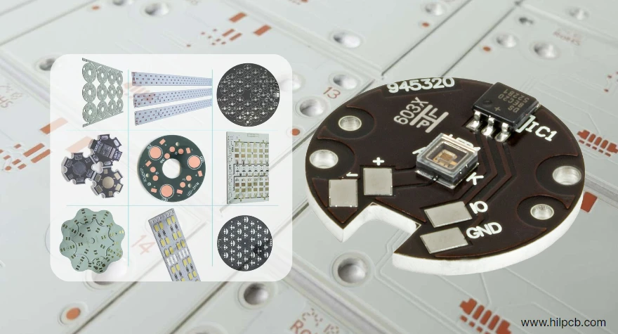
Aluminum PCB manufacturing converts an insulated metal substrate (IMS)—circuit copper bonded through a thermally conductive dielectric to an aluminum base—into a board that moves component heat toward a defined cooling surface while maintaining electrical isolation. Performance depends on the complete thermal and insulation path, not the aluminum label alone.
Key Takeaways
- A common IMS stack is copper, thermally conductive dielectric, and aluminum; multilayer or plated-through constructions need a separately defined build.
- The dielectric often dominates board thermal resistance because it conducts far less heat than aluminum. Compare thermal resistance at the specified thickness and test method, not only headline W/m·K.
- Thinner dielectric can reduce thermal resistance but may reduce electrical withstand and manufacturing margin. Insulation requirements must be solved first.
- Aluminum is conductive. Define insulation around holes, edges, fasteners, chassis contacts, and exposed metal.
- Thicker aluminum can improve stiffness and spreading, but it does not remove heat without a controlled TIM, mounting surface, heatsink, airflow, or other ambient path.
- Copper thickness, trace geometry, current, temperature rise, component footprint, solder joint, dielectric, base plate, and cooling boundary must be analyzed together.
- IMS thermal mass changes soldering behavior; profile the populated board rather than copying an FR-4 reflow recipe.
- Release material, dielectric, copper/base, flatness, isolation, test, inspection, and change-control requirements in the RFQ.
Contents
- What Is an Aluminum PCB?
- How Does Heat Flow Through an IMS Board?
- How Should the Stackup Be Selected?
- What Is the Aluminum PCB Manufacturing Process?
- Which Design Rules Prevent Shorts and Delamination?
- What Quality Evidence Should Be Required?
- How Does Aluminum PCB Assembly Differ from FR-4?
- When Is Aluminum IMS the Right Choice?
- What Should an Aluminum PCB RFQ Include?
What Is an Aluminum PCB?
An aluminum PCB is usually IMS, not FR-4 with metal added afterward. The laminate arrives with copper, filled-polymer dielectric, and aluminum bonded together. The fabricator patterns copper, machines the board, applies mask/finish/marking, then tests and inspects it.
The base spreads heat, adds stiffness, and provides a mounting surface. It is not automatically ground, a finished heatsink, corrosion-proof, lighter than FR-4, or suitable for every harsh environment.
Uses include LED lighting, power converters, motor drives, chargers, relays, and power-control boards. “High power” alone does not prove IMS is best.
How Does Heat Flow Through an IMS Board?
Heat travels from junction through package, solder, copper, dielectric, aluminum, and a mechanical interface to the heatsink, chassis, cold plate, or air. The largest resistance may sit outside the board.
For a uniform layer, the one-dimensional approximation is:
Thermal resistance Rθ = thickness t ÷ (thermal conductivity k × heat-transfer area A)
Real boards add spreading and interface resistance, copper patterning, tolerances, and multiple sources. A higher-conductivity dielectric can perform worse when thicker or measured differently. ASTM D5470 distinguishes thermal impedance and apparent conductivity for heterogeneous insulation; request the test method and specimen.
How Should the Stackup Be Selected?
Thermal-and-insulation decision matrix
| Requirement | Stackup variable | Tradeoff | Evidence to freeze |
|---|---|---|---|
| Junction/case temperature | Dielectric resistance, copper area, base spreading, TIM and cooling boundary | Lower board resistance may not fix a poor interface | Thermal model and instrumented prototype |
| Working/transient voltage | Dielectric thickness/withstand, creepage, clearance and edge isolation | Thinner dielectric reduces insulation margin | Insulation diagram and dielectric test plan |
| Current and temperature rise | Finished copper, trace/plane geometry, terminals and protection | Heavy copper affects etching, spacing, soldering and cost | IPC-2152-informed analysis and measured rise |
| Flatness/mechanics | Aluminum alloy/thickness, outline, copper balance and mounting | Thicker metal adds mass, machining load and thermal inertia | Drawing, flatness condition, fixture and mounting review |
| Assembly | Copper/pad design, mask, finish, panel, thermal mass | Large heat spreading can cause solder-temperature imbalance | Assembly DFM and board-specific thermal profile |
Do not select by a catalog W/m·K class alone. Freeze material designation, dielectric, copper, aluminum alloy/thickness, thermal-impedance data, electrical properties, recognition needs, temperature, availability, and substitutes.
What Is the Aluminum PCB Manufacturing Process?
- Engineering review: Confirm stackup, materials, insulation, geometry, tolerances, panel, finish, tests, and assembly boundary.
- Material preparation: Verify laminate identity, thickness, condition, storage, and lot traceability.
- Imaging and etching: Pattern the circuit copper with compensation for finished copper and required line/space.
- Drilling and profiling: Machine holes, slots, edges, bevels, and breakaways while controlling burrs, debris, tool wear, and dimensions.
- Mask, finish, and marking: Apply the approved solder mask and pad finish; protect designated metal, optical, bonding, or thermal-contact areas.
- Inspection and test: Perform dimensional/visual inspection, electrical test, isolation/dielectric tests, flatness and material/process verification as specified.
Single-layer IMS holes are often non-plated. Plated-through or multilayer metal-backed boards require a purpose-designed insulated-hole construction; aluminum is not ordinary FR-4 dielectric.
Which Design Rules Prevent Shorts and Delamination?
Keep copper away from exposed aluminum edges and mounting features by the validated rule. Account for routing tolerance, burrs, fasteners, debris, chassis contact, and contamination. Solder mask does not replace solid insulation.
Define whether the base floats or bonds to chassis/earth, and where. Unplanned screw contact can create shock, EMC, ground-loop, or short-circuit risk.
Copper imbalance, narrow webs, irregular outlines, and poor mounting affect flatness. Moisture, contamination, machining damage, excessive heat, or incompatible chemistry can initiate delamination.
What Quality Evidence Should Be Required?
| Control | What it verifies |
|---|---|
| Incoming material/lot certificate | Exact IMS family, copper, dielectric and aluminum construction |
| Cross-section or thickness measurement | Copper and dielectric build, interface quality and selected feature geometry |
| Electrical test | Opens and shorts in the circuit pattern |
| Insulation resistance/dielectric withstand | Specified isolation between circuitry and metal base under stated conditions |
| Flatness and dimensions | Fit, assembly support and thermal-interface contact using defined datum/condition |
| Thermal coupon or qualification test | Thermal impedance/conductivity correlation using an agreed method—not inferred from appearance |
| Visual, AOI and edge/hole inspection | Etch, mask, finish, burr, exposed-metal clearance, marking and workmanship |
Thermal cycling, humidity, vibration, salt, or power cycling belong to product qualification when required, not automatically to every lot.
How Does Aluminum PCB Assembly Differ from FR-4?
The metal base changes heat flow, so preheat, peak, time above liquidus, ramp/cool rate, panel loading, support, and rework may differ from FR-4. Profile populated boards at critical locations.
Exposed pads need controlled stencil and solder criteria; more solder or lower voiding is not always better. SMT assembly planning must cover handling, flatness, fixture contact, base isolation, and test access.
When Is Aluminum IMS the Right Choice?
Choose IMS when a planar circuit can move heat into a defined cooling surface and its insulation, routing, cost, weight, and assembly tradeoffs fit. Compare FR-4, copper-base IMS, ceramic, direct-bonded copper, busbars, and power modules.
FR-4 may win when multilayer routing, controlled impedance, weight, plated holes, or cost dominates. Copper and ceramic alternatives change performance, mass, brittleness, assembly, and cost.
What Should an Aluminum PCB RFQ Include?
- Gerber/ODB++/IPC-2581 data, drill/rout files, netlist, drawing, panel, BOM/assembly data and revision
- exact IMS material; dielectric thickness, thermal method/data, electrical withstand, recognition and substitution rules
- finished copper, aluminum alloy/base thickness, outline, holes/slots, edge condition, flatness, dimensions, finish, mask and exposed-metal requirements
- working voltage, insulation, spacing, base grounding, fasteners, TIM, heatsink/chassis, pressure, airflow and ambient
- electrical, isolation, dielectric, dimensional, cross-section, thermal, reliability, sampling, records and traceability requirements
- assembly quantities, components, solder process, profiling, inspection, test, packaging, cleanliness and change-control needs
HILPCB can review the released construction through its metal-core PCB workflow. Final material availability, thermal performance, insulation, product compliance, and qualification must be confirmed against the quoted stackup and finished assembly.
Reference Standards and Test Methods
- IPC-2221 and IPC-2152 — IPC
- IPC-6012 and IPC-TM-650 — IPC
- J-STD-001 and IPC-A-610 — IPC
- ASTM D5470 — ASTM International
- IEC 60664-1 — International Electrotechnical Commission
- UL 796 — UL Standards & Engagement
Applicable editions, product standards, insulation category, recognition scope, and acceptance criteria must be stated by the design authority.
Frequently Asked Questions
Is thermal conductivity the most important aluminum PCB specification?
No. Thickness and area act with conductivity, while interfaces and external cooling can dominate. Electrical withstand may set minimum thickness.
Is an aluminum PCB always better than FR-4?
No. IMS is strong for planar heat transfer into a defined surface. FR-4 can be better for multilayer routing, plated holes, controlled impedance, weight, or cost.
Can the aluminum base be used as ground?
Only when the electrical, safety, EMC, mounting, corrosion, and fault strategy intentionally defines that connection. Accidental grounding through fasteners is not acceptable.
How is aluminum PCB quality tested?
Evidence combines material verification, dimensions/flatness, electrical and dielectric tests, edge inspection, and specified cross-section or thermal coupons. Product qualification is separate.
What causes aluminum PCB delamination?
Risks include an unqualified laminate or process, contamination, moisture, machining damage, poor adhesion, excessive thermal exposure, and incompatible assembly or chemical processes.
Specify the Thermal Path Before Requesting a Quote
An aluminum board works only when its dielectric, copper, metal base, insulation geometry, assembly, mechanical contact, and cooling boundary form one verified path. Send HILPCB the actual thermal and electrical requirements, not only “aluminum PCB,” so the quote can identify a buildable stackup and the evidence needed for release.