
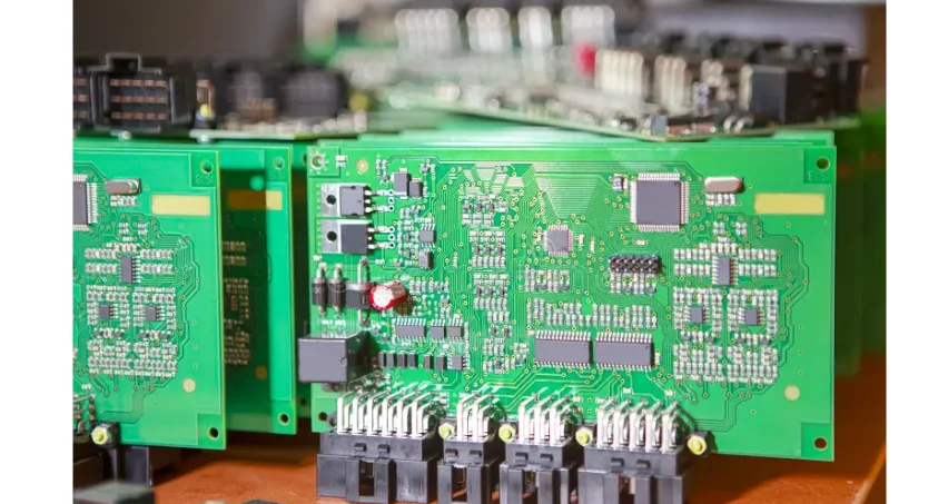
Select an automotive PCB from the circuit’s function and installation conditions. A battery-sensing board, traction inverter controller, radar front end and infotainment motherboard do different jobs; they should not inherit one copper weight, laminate, layer count or inspection plan merely because they are installed in a vehicle.
HILPCB provides multilayer PCB fabrication, high-frequency PCB, heavy copper PCB and PCB assembly routes. Match those capabilities to the released board and customer quality requirements, while keeping vehicle-level safety and validation responsibilities with the product program.
Automotive PCBs in Electric Vehicles: Powering the Future of Transportation
Electric vehicles (EVs) are reshaping the automotive landscape, and automotive PCBs are essential for the operation of EVs. One of the most important aspects of EVs is their battery management systems (BMS), which control charging, discharging, and the overall health of the battery. The PCB supports sensing, communication and control, but battery safety also depends on the BMS architecture, firmware, protection devices and system validation. A cell-monitor board may carry small measurement currents while another assembly handles contactors or pack power; identify that partition before choosing copper and isolation construction. Off the vehicle, the EV charger PCB in a charging station faces similar high-voltage and safety demands.
Moreover, automotive PCBs are integral in the power inverters of electric vehicles. The inverters convert DC (Direct Current) power from the battery into AC (Alternating Current) power that drives the electric motor. These systems require highly reliable and durable automotive PCBs that can withstand high currents, temperature fluctuations, and vibrations, all of which are common in EV environments.
The rising popularity of EVs also means that automotive PCBs are becoming crucial components in the development of electric powertrains, which include systems such as motor controllers, chargers, and power converters. Some powertrain boards need dense control circuitry; others prioritize current paths, insulation or heat transfer. Validate the current and thermal bottlenecks instead of prescribing HDI or a thermal substrate for every EV board. The onboard charger is a good example: an OBC PCB has to handle high voltage, heat, and functional-safety requirements in a compact module.
Automotive PCBs in Autonomous Vehicle Technologies
Autonomous vehicles (AVs) are the next frontier in automotive technology, relying heavily on electronic systems to navigate and make split-second decisions. Automotive PCBs are central to these systems, supporting radar, lidar, and sensor modules that enable real-time object detection and navigation. These systems require precise and fast signal processing, which is made possible by specialized automotive PCBs.
For example, the PCBs for autonomous vehicle radar systems must operate at high frequencies to accurately detect obstacles, while automotive PCBs used in sensor fusion must combine data from multiple sensors to create a cohesive view of the vehicle’s environment. Set reliability and fault-response requirements from the allocated vehicle function and its failure consequences; a display fault and a safety-related sensor fault need different treatment. For high-speed or radar layouts, an impedance calculator can support an initial geometry estimate. Use the selected laminate, finished stackup and channel/antenna model for design signoff, then verify representative coupons and the assembled hardware; the calculator alone does not qualify radar performance.
Additionally, autonomous driving PCBs must manage vast amounts of data from cameras, lidar, and other sensors. These systems are powered by high-speed automotive PCBs designed to maintain signal integrity and reduce the possibility of interference.
Automotive PCBs in Infotainment and Connectivity
The integration of advanced infotainment systems and in-vehicle connectivity has become a standard feature in modern vehicles. From infotainment PCBs that power multimedia systems to PCBs for connectivity modules that enable Bluetooth, Wi-Fi, and 5G communication, these boards are essential in enhancing the driver and passenger experience.
As vehicles become more connected, the role of automotive PCBs in managing vehicle-to-vehicle (V2V) and vehicle-to-infrastructure (V2I) communication becomes even more critical. This interconnectivity supports advancements like autonomous driving, traffic management, and in-car entertainment that relies on real-time data transmission.
Infotainment boards may combine display, audio, storage and network interfaces; cloud-connected navigation or streaming is an additional product feature where implemented. As more features are integrated into vehicle systems, the complexity of automotive PCB designs will continue to grow, requiring more advanced capabilities to handle everything from multimedia processing to security. The Gerber Viewer can help inspect plotted layers and openings before fabrication. It does not replace netlist checks, stackup review, DFM or interface/safety validation.
PCB Designs for Vehicle Surrounding Systems: A Growing Trend
Modern vehicles are not only about the primary internal systems but also the surrounding systems that ensure overall safety and comfort. From automotive PCBs for lighting systems to PCBs for parking sensors, these supporting systems are increasingly reliant on advanced automotive PCB designs.
For instance, automotive PCBs for lighting systems power features like adaptive headlights, taillights, and interior lighting. These systems require PCBs that are resistant to extreme temperatures and vibrations, ensuring long-lasting performance and safety. Similarly, PCBs for parking sensors enable the detection of obstacles around the vehicle, providing essential assistance for drivers, especially in tight spaces.
As the automotive industry pushes toward smarter and more autonomous vehicles, automotive PCBs for vehicle surroundings will continue to be an essential aspect of the driving experience, supporting sensing and controls used in parking assistance and surround-view systems; overall safety performance requires system-level verification.
Match the Vehicle Function to the Manufacturing Route
| Board family | Design decision | Relevant HILPCB route | Evidence to close before release |
|---|---|---|---|
| BMS sensing or control | Sensing error, isolation boundaries, connectors and fault response | Multilayer and SMT/THT assembly | Input-chain calibration, isolation construction and customer-defined functional tests |
| Inverter, OBC or DC/DC power/control | Separate gate-drive/control from high-current and heat paths | Heavy copper or thermal/ceramic options where the actual power path needs them | Current/voltage-drop and thermal results, insulation and attachment checks under defined conditions |
| Radar or other RF sensing | Band, antenna/feed geometry, loss, phase and enclosure interaction | High-frequency/Rogers laminate and approved impedance construction | Material/stackup and coupon acceptance, then assembled RF/antenna validation |
| ADAS compute or infotainment | Processor escape, memory/serial channels, power and cooling | Multilayer, high-speed and density-driven HDI options | Channel/link and load-transient verification, assembly hidden-joint coverage and firmware/test access |
| Lighting or body electronics | Load switching, connector retention, heat removal and exposure | Standard multilayer/assembly; metal-core or other thermal route when justified | Load/fault and temperature checks, coating/enclosure requirements and environmental qualification |
These are route choices, not application approvals. For example, an LED board may benefit from metal-core construction while a radar feed needs a controlled RF stack. Combining their requirements on one assembly needs a reviewed construction, not a blanket claim that the most advanced material fits both.
The Demand for High-Quality Automotive PCBs
With the evolution of the automotive industry, the demand for high-quality, high-performance automotive PCBs has skyrocketed. These boards must be designed to handle high temperatures, vibrations, and harsh environmental conditions while ensuring reliability and efficiency. Whether it's for electric vehicle powertrains, autonomous driving systems, or advanced infotainment, the PCB technology must meet strict industry standards to ensure vehicle safety, durability, and performance. Automotive potting and encapsulation can be considered for specified moisture, vibration or insulation needs. Resin, masking, cure stress, heat flow, rework and the finished enclosure still require evaluation; potting does not by itself qualify a module.
Automotive PCB acceptance and whole-vehicle functional safety have different scopes. ISO 26262 addresses safety-related electrical/electronic systems, including hardware-development requirements; bare-board and assembly acceptance follow the project’s drawings, workmanship and test plan. AEC-Q qualification applies to the relevant components, not automatically to the populated board.
For sourcing, confirm the required production site and quality-system scope, customer-specific requirements and requested approval records. HILPCB’s SMT service lists automotive program controls within the applicable certified scope; an application label is not proof that every site, product or process is covered. Define any requested PPAP, change-control, material/lot linkage and inspection/test records in the quality agreement. Turnkey traceability can be batch level or quoted unit-level serialization; request the granularity the program needs.
Innovations in Automotive PCB Manufacturing
As the automotive industry continues to innovate, so too must the PCB manufacturing process. The demand for smaller, more efficient, and highly integrated automotive PCBs is driving innovations in PCB design, materials, and manufacturing techniques. For example, new technologies like flexible PCBs are being used in automotive applications where traditional rigid PCBs are not suitable, such as in compact or curved spaces.
Evaluate changes through the constraint they resolve. HDI may reduce a fine-pitch escape problem but adds build-up and inspection steps. Rigid-flex may remove a connector but introduces bend/support requirements. Low-loss material may help an RF or serial channel but is not a substitute for current-carrying copper or a heatsink. Compare unit price, tooling, test coverage, assembly yield assumptions and the cost of a qualification change before approving the upgrade.
Quote the Released Automotive Board and Build Scope
For a HILPCB fabrication or turnkey assembly review, send fabrication/drill data, stackup, impedance requirements, netlist, BOM with approved part numbers, placement/assembly drawings and quantities. Identify the board’s vehicle function, installation zone, supply/load waveforms, operating voltage, cooling and mechanical/connector constraints. Mark isolation, RF, flex-bend or coating features that affect the manufacturing route.
For assembled builds, include firmware/programming assets, test access, fixtures, stimulus/load conditions and pass/fail limits. State required material provenance, lot or unit traceability, inspection reports, change approval and customer qualification documents. Ask the quotation to identify the selected manufacturing site/route, open DFM items, approved substitutions, tooling/test costs and delivery basis after material/BOM review. The first build should close named risks—such as a hot connector, sensor error or marginal RF feed—before the program freezes its production baseline.
Frequently Asked Questions
Does an automotive PCB supplier need IATF 16949 certification?
Certification needs depend on the customer and supply-chain role. Where IATF 16949 is required, verify the legal entity, production site, current certificate and applicable scope. Separately agree customer-specific approval and PPAP requirements. AEC-Q component qualification and vehicle functional safety are different evidence layers.
What PCB qualification evidence matters for EV electronics?
Start with the board function and mission profile: voltage/current and fault conditions, temperature/vibration, moisture, insulation and any safety allocation. Define fabrication and assembly acceptance, then specify representative current/thermal, interface and environmental tests with conditions and limits. A coupon or workmanship pass does not replace the complete EV module’s qualification.