
PCB Assembly & Circuit Card Assembly (CCA) Services | SMT, NPI & Turnkey
Agile PCB assembly and circuit card assembly (CCA) services for hardware engineering and procurement teams. From 24-hour quickturn SMT prototypes to high-volume manufacturing, HilPCB delivers automated SMT placement (10M+ daily points), DFM/DFT verification, global BOM sourcing, and 100% 3D AOI/X-ray inspection.
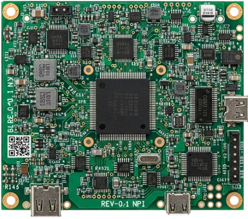
PCB Assembly Services: SMT, Through-Hole, and Mixed-Technology Routes
A board that needs placement, soldering, inspection, and test starts with a scope review: board type, component mix, volumes, test intent, and sourcing responsibility. The review routes the request to the appropriate assembly service.
Mixed technology PCB assembly combines surface-mount and through-hole parts on one controlled build route, so the quotation should define solder sequence, inspection coverage, test access, and the ownership of any component sourcing.
Choose SMT assembly when surface-mount placement and reflow are the main requirement. Choose through-hole assembly for connectors, terminals, relays, transformers, or selective and wave soldering. Use small-batch assembly for prototype and NPI learning, large-volume assembly for a stable repeat program, and turnkey assembly when BOM ownership and component sourcing belong in the same workflow.
- Best fit: released PCB data that needs a manufacturable assembly route
- Scope review: board construction, component mix, quantity, test, and delivery stage
- Boundary: box build adds enclosure, cable, firmware, and final configuration work
- Escalation path: prototype and NPI learning before repeat or volume production
🚀 Quick Quote Request
📋 Get Full Capabilities
Circuit Card Assembly (CCA) & SMT Volume Manufacturing
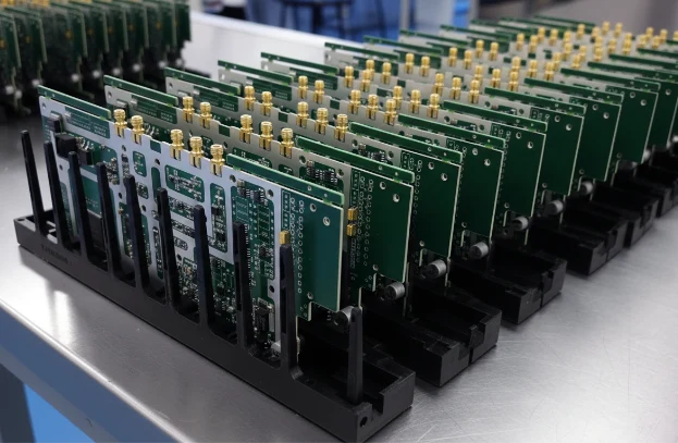
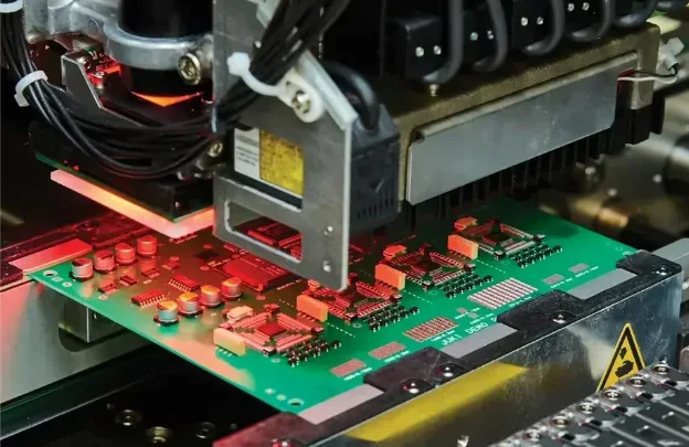
Whether your program calls for commercial board assembly or mission-critical circuit card assembly (CCA), HilPCB bridges the gap between rapid NPI iterations and cost-optimized volume manufacturing. Our facility operates multiple high-speed Fuji and Yamaha SMT lines supporting components down to 01005 passives and 0.35mm pitch BGAs/QFNs.
For engineering startups and tier-one OEMs alike, our turnkey PCB assembly model eliminates supply chain friction: upload your Gerber and BOM files to receive an itemized quote within 2 hours. We procure authentic parts through authorized franchised distributors (DigiKey, Mouser, Arrow), verify solderability in-house, and transition seamlessly from 24-hour pilot builds to scalable production runs of tens of thousands of units.
- Full support for commercial PCBA and aerospace/industrial Circuit Card Assembly (CCA)
- 01005 micro-chip and 0.35mm micro-BGA placement with ±15µm accuracy
- 24-hour rapid prototyping turnarounds for quick design validation
- In-house BOM kitting with direct authorized distributor procurement
📋 Get Full Capabilities
DFM/DFT Review and NPI Handoff for PCB Assembly
DFM/DFT for PCB assembly connects the released design to placement, soldering, inspection, and test access before fixtures, programs, and production records are released.
The first review connects design intent to the assembly process: land patterns, component orientation, spacing, fiducials, panelization, thermal balance, solderability, and test access. DFT review identifies what can be inspected or tested before fixtures and programs are released.
During NPI, build feedback is recorded against the revision, stencil, placement data, reflow profile, and test plan. Open issues are separated into design changes, process adjustments, and material or sourcing decisions so the next build has an explicit release basis. Stable designs can then move to volume assembly; programs that need enclosure and final configuration can move to box build assembly.
- DFM checks for pads, spacing, orientation, panelization, and thermal balance
- DFT checks for test points, fixture access, programming, and functional coverage
- Revision-controlled NPI feedback and release decisions
- Clear handoff from pilot evidence to repeat or volume production
PCB Assembly Inspection, Test, and Release Evidence
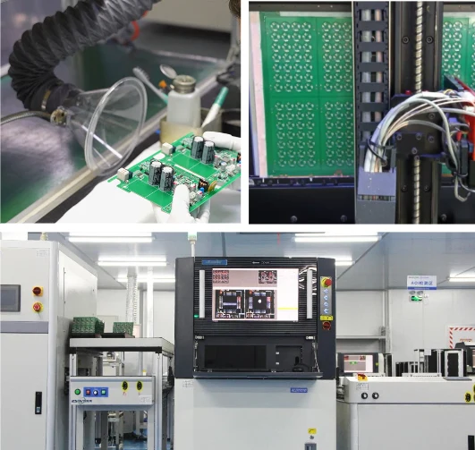
Inspection and test are selected against package risk, product criticality, and the customer test plan. Typical routes combine 3D solder-paste inspection, AOI, visual workmanship review, and electrical or functional testing; X-ray, flying probe, ICT, boundary scan, burn-in, or cleanliness checks are added when the design and acceptance criteria call for them.
The deliverable is more than a pass/fail statement. A release package can include inspection records, reflow profile data, test results, nonconformance disposition, lot or serial traceability, and the revision used for the build. The exact evidence set is agreed during quotation and NPI planning.
- 3D SPI and AOI for solder-paste and placement evidence
- X-ray for hidden joints or other package-specific risks
- ICT, flying probe, FCT, boundary scan, or customer-defined test coverage
- Inspection, test, revision, and traceability records aligned to the release
🚀 Quick Quote Request
Assembly Route and Sourcing Model Selection Matrix
Match your design constraints and procurement situation to the right assembly route, sourcing model, and evidence level
| Design or procurement input | Recommended assembly route | Recommended sourcing model | Required RFQ evidence | Risk owner |
|---|---|---|---|---|
Surface-mount packages (QFN, BGA, fine-pitch ICs) | SMT placement and reflow | Full turnkey or partial turnkey | Gerber, BOM, CPL, reflow profile notes | |
Through-hole parts (connectors, relays, transformers) | THT or mixed technology | Consigned or partial turnkey | Assembly drawing, solder sequence, selective or wave notes | |
Mixed SMT + THT on one board | SMT first, then selective or wave soldering for THT | Full turnkey for BOM control | Gerber, BOM, CPL, solder sequence, inspection plan | |
Prototype or NPI (1-50 boards) | Small-batch assembly with DFM/DFT review | Partial turnkey or consigned | Gerber, BOM, CPL, test intent, revision status | |
Stable repeat program (1,000+ boards) | Volume assembly with locked process | Full turnkey for cost and lead-time control | Released Gerber, approved BOM, forecast, test fixtures | |
BOM ownership needed (sourcing, alternates, lifecycle) | Turnkey assembly | Full turnkey - HilPCB owns sourcing | BOM with MPNs, AVL, alternates, compliance requirements | |
Product needs enclosure, cable, firmware, final test | Box build assembly | Full turnkey with system-level test | Full assembly data, mechanical drawings, firmware, test spec | |
IPC-A-610 Class 3 (medical, automotive, aerospace) | SMT/THT with enhanced inspection and X-ray | Full turnkey with documented test plan | IPC class, acceptance criteria, traceability, FAI/COFC |
Need capabilities beyond this product? Explore our full manufacturing capabilities
Ready to start your PCB project?
Whether you need simple prototypes or complex production runs, our advanced manufacturing capabilities ensure excellent quality and reliability. Get your quote within 30 minutes.
Circuit Card Assembly (CCA) Services: Precision Standards and Agile Production
In modern electronics manufacturing, Circuit Card Assembly (CCA) represents the standard industrial term for fully populated, inspected, and tested circuit boards engineered for demanding operational environments. While general consumer board assembly often operates on visual sampling under IPC Class 2, HilPCB's Circuit Card Assembly workflow incorporates rigorous process validation:
- Precision SMT & THT Placement: High-speed automated placement heads handle mixed-technology boards combining 01005 passives, PoP (Package-on-Package), fine-pitch QFNs, and heavy through-hole connectors.
- Automated In-Line Inspection: Every circuit card passes through 3D Solder Paste Inspection (SPI) prior to placement, followed by multi-angle 3D AOI and automated X-ray inspection (AXI) for BGA/QFN hidden joints to ensure voiding rates remain well below international limits (< 15%).
- Functional Testing & Traceability: Complete flying probe testing, in-circuit testing (ICT), functional test (FCT), and serialized barcode tracking guarantee full accountability across every delivered board.
Explore our specialized SMT assembly and box build assembly pages to learn how we integrate board-level electronics into complete systems.
SMT, THT, or Mixed: Which Assembly Technology Fits Your Board
Most production boards use a mix of SMT and through-hole components. The decision is not which technology is better - it is which combination matches your component mix, density, reliability target, and repair requirements.
Choose SMT when the board is dominated by surface-mount packages: QFN, BGA, fine-pitch ICs, and passive devices down to 01005. SMT delivers higher placement density, faster throughput, and lower per-joint cost at volume. Reflow soldering controls the thermal profile for most lead-free joints in one pass.
Choose through-hole (THT) for connectors that carry mechanical load or high current, transformers, relays, large capacitors, and any part specified for wave or selective soldering. THT joints are stronger under vibration and thermal cycling, and through-hole parts are easier to rework by hand.
Choose mixed technology when both categories appear on the same board. The typical sequence is SMT paste printing, placement, and reflow first, then through-hole soldering via selective or wave soldering, followed by combined inspection. Mixed-technology boards require a solder sequence review to avoid reflow damage to THT parts and to ensure THT solder does not disturb SMT joints.
For a deeper process comparison, see the circuit board assembly guide and the SMT assembly process article.
Turnkey, Partial Turnkey, or Consigned: Who Owns Component Risk
The sourcing model determines who buys components, who owns shortage and attrition risk, and how alternates are approved. The choice affects cost, lead time, and the amount of procurement work your team must do.
Full turnkey - HilPCB purchases all components, owns BOM review, sources alternates, and manages lifecycle risk. You send the BOM and approved vendor list; we handle procurement, expediting, and shortage response. Best for teams that want a single point of accountability and faster lead times. Risk owner for shortages and attrition: HilPCB.
Partial turnkey - You supply specific controlled or long-lead parts (e.g., allocated ICs, custom connectors); HilPCB sources the rest. Best when you have allocated inventory or preferred pricing on specific components. Risk owner for supplied parts: you. Risk owner for sourced parts: HilPCB.
Consigned (kitted) - You supply all components, kitted and labeled to the BOM. HilPCB performs assembly, inspection, and test. Best when you control proprietary parts or have existing supply contracts. Risk owner for kit completeness, part correctness, and shortages: you.
Under every model, HilPCB records lot codes, date codes, and supplier traceability against the build revision. The division of responsibility is documented in the quotation before the build starts.
What Inspection and Test Coverage Does Your PCBA Need?
Inspection and test are not one-size-fits-all. The right coverage depends on package risk, board complexity, acceptance class, and the cost of a field failure. Plan test coverage during RFQ and NPI using the criteria below.
3D SPI (solder paste inspection) - baseline for SMT boards. Catches paste volume and registration errors before reflow. Recommended for all SMT builds.
AOI (automated optical inspection) - baseline for placement and post-reflow solder quality. Catches missing, misaligned, or tombstoned components, solder bridges, and insufficient solder. Recommended for all production builds.
X-ray - required for BGA, QFN, and any hidden-joint package where visual inspection cannot verify solder coverage. Added when the package mix includes area-array devices or when IPC-A-610 Class 3 applies.
ICT (in-circuit test) or flying probe - verifies electrical connectivity and component values before functional test. ICT needs a bed-of-nails fixture and is cost-effective at volume; flying probe is fixtureless and fits prototype or low-volume runs. Choose ICT when the board has test pads and the volume justifies fixture cost; choose flying probe when volumes are low or the design is not yet test-pad optimized.
FCT (functional test) - validates that the board performs its intended function under operating conditions. Required when the product specification defines functional acceptance. The test plan and fixture are agreed during NPI.
Boundary scan - tests digital interconnects without physical probe access. Useful for high-density boards where ICT pads are not feasible. Requires JTAG-compatible devices and a boundary scan netlist.
Burn-in - accelerates early-life failures through elevated temperature and voltage stress. Added for reliability-critical products or when the customer specification calls for it.
The evidence from each stage - SPI data, AOI images, X-ray results, test logs, nonconformance records - is compiled into the release package. The exact set is agreed during quotation. For defect-mode detail, see the BGA soldering defects guide.
IPC-A-610 Class 2 vs Class 3: Which Acceptance Standard Applies
The acceptance class determines how much solder, alignment, and cleanliness variation is allowed. Specifying the wrong class leads to over-inspection cost (Class 3 on a consumer product) or reliability risk (Class 2 on a medical device). Confirm the required class in the RFQ so inspection criteria and evidence are aligned from the start.
IPC-A-610 Class 2 - general electronic products where cosmetic imperfections are tolerated if function and reliability are not compromised. Typical applications: consumer electronics, industrial controls, IoT devices, and most prototype builds. HilPCB inspects to Class 2 by default unless a higher class is specified.
IPC-A-610 Class 3 - high-reliability products where extended life and uninterrupted service are critical. Typical applications: medical equipment (ISO 13485 scope), automotive electronics (IATF 16949 scope), aerospace, defense, and safety-critical systems. Class 3 requires tighter solder volume, alignment, and cleanliness limits, and may add X-ray, burn-in, or cleanliness testing to the evidence set.
Related standards that may apply depending on the product: J-STD-001 for soldering requirements, J-STD-020 for MSL classification and moisture handling, IPC-7711/7721 for rework and repair procedures, and ANSI/ESD S20.20 for ESD control. State the applicable standards and acceptance class in the RFQ so the process, inspection, and documentation are configured correctly.
What Files Do You Need for a PCB Assembly Quote?
Use this checklist to prepare a complete RFQ. Missing or incomplete files are the most common cause of quotation delays and process ambiguity.
- Gerber or ODB++ files - fabrication data, drill data, and board outline. Missing: cannot quote fabrication or verify panelization.
- BOM with MPNs - manufacturer part numbers, reference designators, quantities, and approved alternates. Missing: cannot source components or assess lifecycle risk.
- Centroid / placement file (CPL) - X/Y coordinates, rotation, and side of board for each component. Missing: cannot program pick-and-place or verify orientation.
- Assembly drawing - component locations, polarity markings, special soldering notes, and exclusion zones. Missing: risk of misplacement or missed special-process requirements.
- Stackup and impedance notes - layer order, dielectric thicknesses, copper weights, and controlled-impedance requirements. Missing: cannot verify fabrication compatibility with assembly thermal profile.
- Test requirements - IPC class, inspection level, electrical test method (ICT/flying probe/FCT), and acceptance criteria. Missing: inspection and test plan cannot be configured.
- Quantity and schedule - prototype, NPI, or production volume; target delivery date; and forecast or repeat-build expectation. Missing: cannot allocate line time or assess sourcing lead time.
- Sourcing rules - consigned parts list, sourcing restrictions, AVL, substitution authority, and compliance or traceability constraints. Missing: sourcing model and risk ownership cannot be defined.
Send these files and decisions to request a quote. The review team confirms the assembly route, sourcing model, test plan, and evidence set before pricing.
PCB Assembly Engineering Examples by Industry and Application
These are common engineering scenarios that HilPCB reviews and routes according to the released design, package mix, material set, inspection plan, and test requirements. Use the same questions during RFQ review: what is the package risk, which process gate controls it, and which evidence must be delivered?
High-speed compute and server boards. Dense BGA populations, high thermal mass, and fast interfaces require package-land-pattern review, stencil and support-pin planning, a thermal profile matched to component limits, and agreed AOI/X-ray and electrical coverage. Route: SMT with X-ray, full turnkey for BOM control. See the AI server motherboard assembly guidance for the design-to-assembly risk chain.
Mixed-technology industrial controls. Surface-mount ICs combined with through-hole connectors, relays, and terminal blocks. The solder sequence - SMT reflow first, then selective or wave soldering for THT - must avoid thermal damage to THT parts and ensure THT solder does not disturb reflowed SMT joints. Route: mixed technology, partial turnkey if controlled parts are involved.
Medical device PCBA (ISO 13485 scope). Class 3 acceptance, full traceability from lot code to board serial number, documented reflow profiles, X-ray for hidden joints, cleanliness testing if specified, and a release package that supports regulatory submission. Route: SMT or mixed with enhanced inspection, full turnkey with documented test plan.
Automotive ECUs (IATF 16949 scope). Class 3 acceptance, AOI and X-ray coverage, boundary scan or ICT for electrical test, burn-in if the specification calls for it, and PPAP-level documentation. Route: SMT or mixed with full test coverage, full turnkey for supply-chain control. See the automotive radar manufacturing guide for the assembly-to-validation chain.
Prototype validation builds. Small quantity (1-50 boards), design not yet frozen, test coverage still being defined. Route: small-batch assembly with DFM/DFT review, consigned or partial turnkey, flying probe for electrical test, and NPI feedback recorded against the revision for the next build.
What Drives PCB Assembly Cost and Lead Time?
PCB assembly cost and lead time are driven by four factors: board complexity, component sourcing, volume, and test coverage. Understanding these drivers helps you prepare an RFQ that produces an accurate quote without rounds of clarification.
Board complexity. Double-sided placement, fine-pitch QFN/BGA, mixed SMT and through-hole, and high component count all increase setup, programming, and processing time. Boards with 01005 passives or sub-0.4 mm pitch packages require tighter process windows and more inspection.
Component sourcing. Full turnkey sourcing adds procurement lead time but reduces your coordination effort. Consigned kits eliminate sourcing time but require you to deliver complete, verified, and properly packaged parts. Allocated or long-lead components extend lead time under any model; approved alternates shorten it.
Volume. Prototype and small-batch builds (1-50 boards) typically ship in 3-7 working days after design release. Production runs (1,000+ boards) require stencil fabrication, fixture preparation, and first-article approval before ramp, with recurring build lead time depending on component availability and line scheduling.
Test coverage. SPI and AOI are baseline and add minimal time. X-ray, ICT, flying probe, FCT, boundary scan, and burn-in each add programming, fixture, or processing time. Specifying the required test plan in the RFQ prevents delays during NPI.
For an accurate quote, state the quantity, target delivery date, sourcing model, and test requirements alongside the design files. The review team confirms the route, identifies long-lead or allocated components, and returns a price and schedule based on the released data.
PCB Assembly Supplier for SMT, THT, Mixed-Technology, and CCA Programs
HilPCB serves as a PCB assembly supplier for design teams that need a released board built, inspected, and tested. The same review covers SMT assembly, through-hole assembly, mixed technology, and circuit card assembly (CCA), so the route follows the actual package population rather than a generic service label.
Choose PCB assembly when one team needs to coordinate DFM/DFT review, sourcing responsibility, inspection, test, and release records. Start with small-batch PCB assembly for prototype or NPI learning, or with turnkey PCB assembly when BOM ownership and component procurement are part of the request.
Frequently Asked Questions
What is the difference between Circuit Card Assembly (CCA) and standard PCB assembly?
How fast can HilPCB deliver prototype PCB assemblies and CCAs?
What component sourcing options do you offer for turnkey assembly?
Can you assemble both SMT and through-hole components on one board?
What is the difference between PCB assembly and turnkey assembly?
What is the typical lead time for PCB assembly?
What components and package types can you assemble?
What files do I need to send for a PCB assembly quote?
Who owns component shortage and attrition risk under each sourcing model?
Do you support IPC-A-610 Class 3 for medical, automotive, or aerospace applications?
Experience Advanced PCB Manufacturing Excellence
From simple prototypes to complex production runs, our world-class factory delivers superior quality, fast turnaround and competitive pricing. Join thousands of satisfied customers who trust us with their PCB manufacturing needs.