
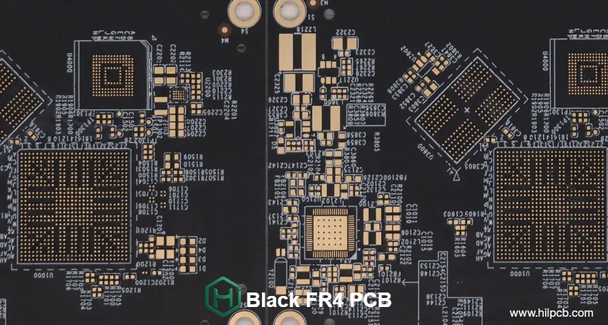
Black FR4 PCB selection should be based on whether the project needs optical control, premium appearance, thermal improvement, or a manufacturing-compatible finish. Engineers should decide between standard FR4 with black solder mask, high-Tg FR4, or alternative thermal PCB structures by reviewing operating temperature, dielectric requirements, copper weight, layer count, inspection capability, and supplier evidence. The key evidence to request is a controlled stackup, material data sheet, cross-section report, thermal test data where applicable, and process capability documentation.
What should engineers verify before choosing a black FR4 PCB?
Black FR4 PCB is usually selected for products where visual appearance and optical performance matter, including gaming hardware, automotive displays, premium consumer electronics, and professional audio equipment. The black appearance typically comes from the solder mask layer rather than a change to the FR4 laminate itself.
The engineering decision is not simply “black versus green.” The decision is whether black solder mask provides enough product value to justify additional manufacturing complexity.
Important evaluation factors include:
- Optical reflection requirements for displays, cameras, and sensors
- Thermal behavior of the complete assembly rather than solder mask color alone
- Operating temperature requirements
- Required copper thickness and current capacity
- Layer count and routing density
- Inspection capability for black solder mask surfaces
- Assembly requirements for component identification
A black FR4 PCB can support premium product positioning, but thermal performance is normally determined by copper area, stackup, dielectric material, vias, heatsinking, airflow, and component selection.
Does black solder mask improve PCB thermal performance?
Black solder mask can improve radiation characteristics because darker surfaces generally have higher emissivity than lighter surfaces. However, the actual temperature reduction depends on the complete thermal design.
The original design target for black FR4 PCB applications often includes:
- Emissivity factor: 0.90-0.95 compared with approximately 0.85 for green FR4 PCB
- LED application temperature improvement claims of 5-8°C lower junction temperature
- Thermal cycling evaluation through 1500+ cycles
These values should be validated against the actual assembly because solder mask color alone does not replace thermal engineering methods such as copper planes, thermal vias, metal cores, or higher thermal conductivity materials.
For higher thermal demands, compare standard FR4 dielectric thermal conductivity ranges:
| Parameter | Typical engineering range | Risk if ignored | Evidence to request |
|---|---|---|---|
| Standard FR4 dielectric thermal conductivity | 1.5-3 W/mK | Hot spots around power components | Material datasheet and stackup |
| High-performance thermal dielectric | 4-8 W/mK | Insufficient heat spreading in high-power designs | Thermal conductivity report |
| Black solder mask emissivity | 0.90-0.95 typical target range | Incorrect thermal assumptions from color alone | Thermal test method and results |
| Thermal cycling capability | 1500+ cycles used in some application targets | Cracking or reliability failures | Reliability test report |
When should a project use black FR4 PCB instead of standard FR4?
Gaming hardware and premium consumer electronics
Black FR4 PCB is widely used where appearance is part of the product experience. Matte black surfaces reduce visible reflections inside RGB-illuminated systems and create visual consistency with premium enclosures.
For these applications, engineers should verify:
- White silkscreen readability
- Component identification during assembly
- Cosmetic inspection standards
- Scratch and contamination visibility
Automotive electronics
Automotive displays and infotainment systems often require low-reflection surfaces. Black solder mask can reduce visible contrast problems inside display assemblies.
Automotive designs should also evaluate:
- Operating temperature range
- High-Tg material requirements
- Moisture resistance
- Long-term thermal cycling
For harsh environments, high-Tg FR4 materials are commonly selected. Typical high-Tg options may target Tg ranges such as 165-180°C depending on laminate selection.
Premium audio equipment
High-end audio products may use black PCBs for visual integration with metal chassis designs. Black solder mask may provide marginal EMI-related benefits, but it should not replace dedicated shielding or grounding design.
A reported application consideration is approximately 3dB additional attenuation at 1GHz from carbon-content effects. Engineers should confirm EMI performance through testing rather than relying on solder mask color.
How do black solder mask and black-core FR-4 compare?
Many projects that specify "black FR4" only need black solder mask applied to a standard FR-4 laminate. Black-core FR-4—where the substrate itself is pigmented black—is a separate, less common option with different optical, procurement, and cost implications. The decision matrix below separates the two so engineers can avoid paying for black-core material when surface-level black is sufficient.
| Property | Black solder mask on FR-4 | Black-core FR-4 |
|---|---|---|
| Appearance | Surface only | Full opacity |
| Optical opacity | Partial | Complete |
| IR emissivity | 0.90–0.95 | Similar |
| Thermal conductivity | ~0.3 W/mK dielectric | Same FR-4 |
| Tg range | 130–180°C | 130–180°C |
| AOI contrast | Low | Low |
| Cost premium | +10–20% | +50–100% |
| Lead time | Standard | Extended |
| Availability | Standard | Limited supply |
Black solder mask on FR-4 covers the majority of premium-appearance and low-reflection use cases at a modest cost premium. Black-core FR-4 is reserved for applications requiring complete optical opacity through the substrate—such as light-blocking barriers in camera modules or display assemblies—where any light transmission through the board edge or via barrels is unacceptable. Engineers should confirm with the supplier whether a black-core quote is genuinely pigmented laminate or simply black solder mask on standard FR-4 before approving the cost difference.
What manufacturing risks exist with black solder mask PCB?
Black solder mask creates several production challenges compared with traditional green solder mask.
How does black solder mask affect PCB inspection?
Black surfaces reduce contrast between solder mask and copper features. Automated optical inspection systems may require:
- Higher-resolution cameras
- Specialized lighting angles
- Enhanced defect detection algorithms
Supplier capability should be verified with sample inspection records and defect detection examples.
How does black solder mask affect coating control?
Carbon additives can affect solder mask flow characteristics. Manufacturing controls should include:
- Solder mask thickness monitoring
- Viscosity control
- Coating uniformity inspection
A typical black solder mask thickness range is approximately 10-15μm depending on process and supplier specification.
What quality checks should be requested?
Recommended verification includes:
- UV inspection for coverage verification
- Cross-section analysis at 200X magnification
- Adhesion testing per IPC-TM-650
- Ionic contamination testing using supplier-defined parameters
What black FR4 PCB specifications should be compared during supplier selection?
A procurement comparison should focus on measurable manufacturing capability rather than appearance claims.
| Specification | Selection consideration | Verification method |
|---|---|---|
| Layer count | Single-layer through multilayer designs may be required | Stackup drawing |
| Board thickness | Common FR4 thickness examples include 1.6mm; supplier capability varies | Mechanical drawing |
| Copper thickness | Typical PCB copper options include 0.5-4oz depending on design requirements | Copper weight report |
| Minimum line width/spacing | Advanced boards may require 4/4mil capability | Capability report and coupon |
| Minimum hole size | Production examples range from 0.1mm to 0.3mm depending on supplier process | Drill chart |
| Dielectric constant Dk | FR4 commonly ranges approximately 4.3-4.7 at 1MHz-1GHz | Material datasheet |
| High-frequency black solder mask | Optimized materials may report 3.1-3.4 Dk at 1GHz | Solder mask material data |
| Voltage requirements | Define insulation and clearance requirements from design rules | PCB design specification |
What stackup options are available for black FR4 PCB?
Black FR4 PCB can be manufactured in configurations ranging from simple two-layer boards to advanced multilayer constructions.
Common configurations include:
- 2-layer FR4 with black solder mask and ENIG finish
- 4-layer FR4 designs for consumer electronics
- 8-16 layer constructions for industrial and automotive systems
- HDI structures with microvias
Typical industry examples include:
- Board thickness: 0.5-6.0mm substrate range depending on construction
- Overall board thickness: approximately 0.8-7.5mm depending on layer count
- Thickness tolerance: approximately ±0.08mm for boards ≥0.8mm
- Inner copper: 0.5-2oz (17-70μm)
- Outer copper: 1-3oz (35-105μm)
For RF-related designs, FR4 dielectric constant and loss characteristics should be reviewed carefully. Standard FR4 may not be the correct choice for every high-frequency application.
How much does black FR4 PCB cost compared with standard PCB finishes?
Black FR4 PCB usually carries additional manufacturing considerations because of inspection and process control requirements.
The original cost factors include:
- Raw material increase: +$0.15-0.25/ft²
- Extended inspection time: +20% labor
- Lower yield rates: 2-3% reduction
- Specialized tooling considerations for multilayer FR4 PCB
The value decision depends on product requirements:
- Premium product appearance
- Reduced optical interference
- Design consistency with enclosure materials
- Potential thermal radiation advantages
For consumer products where appearance affects product positioning, the added cost may be justified at higher production volumes.
What files and specifications should be included in a black FR4 PCB RFQ?
A complete RFQ package reduces quotation errors and allows suppliers to recommend the correct process.
Submit:
- Gerber files
- PCB fabrication drawings
- BOM file
- Complete stackup requirements
- Layer count requirement
- Copper weight requirements
- Via drawing
- Drill files
- Mechanical dimensions
- Impedance requirements
- Surface finish requirement
- Solder mask color requirement
- Silkscreen requirements
- Assembly drawings if PCBA service is required
Request supplier evidence:
- Material datasheet
- FR4 laminate specification
- Solder mask technical data
- Cross-section report
- Thermal test report if thermal improvement is a design requirement
- Electrical test report
- Inspection criteria
- Capability documentation for minimum trace, spacing, and via size
How should black FR4 PCB designs be optimized for assembly?
Black surfaces require additional attention during assembly because component references are less visible than on lighter solder masks.
Recommended design practices:
- Use white silkscreen for maximum contrast
- Maintain minimum text height of 0.8mm for reliable legibility
- Add clear polarity indicators
- Provide detailed assembly drawings
- Confirm inspection lighting conditions
Exposed copper can appear brighter against black solder mask, which may help debugging but can affect cosmetic requirements.
Consider alternative finishes such as yellow FR4 PCB where safety markings require maximum visibility, or white FR4 PCB where trace visibility and optical presentation require different characteristics.
Black FR4 PCB manufacturing capability requirements
A qualified supplier should support:
- Matte and glossy black solder mask options
- 10-30μm thickness control
- single layer FR4 PCB through complex multilayer PCB manufacturing
- HDI and embedded component compatibility
- Selective black/green solder mask options for cost optimization
The correct supplier choice depends on balancing appearance, thermal requirements, electrical performance, and production risk.
For premium electronics, black FR4 PCB is most effective when the finish selection is part of a complete engineering decision covering material, stackup, thermal design, and manufacturing verification.
HILPCB supports black FR4 PCB production for applications requiring controlled aesthetics and engineering performance. Review options alongside premium FR4 PCB solutions to select the correct manufacturing approach for your product requirements.