
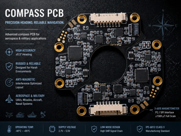
Electronic compasses measure the Earth's magnetic field to determine heading — the direction a platform is pointing relative to magnetic north. The global electronic compass market reached $2.4 billion in 2023, driven by smartphone integration, automotive navigation, UAV autopilots, and military heading reference systems. Yet the PCB design challenge remains deceptively complex: the Earth's field is weak (25–65 μT depending on latitude), and a typical PCB generates interference 10–100× stronger from its own ferrite inductors, switching regulators, and current-carrying traces.
HILPCB fabricates compass PCBs from $3 consumer drone modules through $1,500 naval defense heading references — with over 150 magnetometer board programs delivered across navigation markets in North America, Europe, Scandinavia, and Australia. Our DFM review specifically includes magnetic interference analysis that most fabricators do not offer.
In This Guide
- MEMS Magnetometer PCB Layout for Magnetic Cleanliness
- Fluxgate Compass Signal Chain and PCB Isolation
- Magnetic Interference Calibration and Tilt Compensation
- Marine, Military, and UAV Compass Applications
- Production Calibration and Magnetic Cleanliness Testing
- HILPCB Compass and Navigation PCB Programs
MEMS Magnetometer PCB Layout for Magnetic Cleanliness
The magnetometer is one of the few sensors where the PCB layout itself is the dominant source of measurement error. Unlike accelerometers or gyroscopes where mechanical mounting matters most, the compass sensor fights against the electromagnetic environment its own board creates. A ferrite inductor on the same board generates 50–500 μT at 10 mm — up to 10× the Earth's field the sensor is trying to measure.Modern 3-axis magnetometers from Bosch (BMM350), STMicroelectronics (LIS3MDL, ±30 μT range), and Memsic (MMC5983MA, ±8 gauss) provide digital SPI/I²C output. The PCB interface requires clean power (100 nF + 10 μF within 1 mm), proper bus connections, and correct physical orientation — but achieving rated heading accuracy demands far more:
- Component Placement: Magnetometer ≥15 mm from ferrite inductors, switching regulators, motors, and speakers. Non-magnetic shielding cans and non-ferrous hardware (aluminum, brass, 316 stainless) within the 20 mm exclusion zone.
- Current Loop Cancellation: High-current traces routed as closely-spaced forward/return pairs on the opposite board side from the sensor — cancelling external magnetic fields through geometric symmetry.
- Non-Magnetic Materials: Tin-plated headers replacing nickel-plated. ENIG surface finish is magnetically clean; HASL with nickel barrier may not be, depending on the alloy composition.
- Dedicated LDO Power: A separate low-noise LDO for the magnetometer rail eliminates switching regulator magnetic noise entirely — a $0.30 component that can improve heading accuracy by 2–5°.
Fluxgate Compass Signal Chain and PCB Isolation
Fluxgate magnetometers achieve 10–100× better resolution than MEMS — enabling ±0.1–0.5° heading accuracy required by naval navigation systems meeting IEC 62672 and geodetic survey instruments used by mapping agencies across Norway, Canada, and the United States. The global marine compass market exceeds $400 million annually, with fluxgate heading references commanding premium pricing justified by their sub-degree accuracy.A fluxgate uses a permalloy core driven into saturation by an excitation oscillator (10–50 kHz). The second harmonic of the sense coil output is proportional to external field strength. The PCB must prevent excitation oscillator fields from coupling into the sense amplifier — routing excitation current in tightly coupled differential pairs (loop area <1 mm²), placing sense and drive sections at opposite board ends, and using stripline routing on multilayer boards for shielded sense signals with separate analog/digital ground planes connected at a single point.
For sub-degree accuracy, excitation amplitude must be stable within ±0.1%, and the demodulator reference clock must have jitter below 1 ns. HILPCB's fluxgate compass boards achieve these specifications through precision analog layout validated by post-assembly magnetic cleanliness measurement at the sensor location.

Magnetic Interference Calibration and Tilt Compensation
Every compass PCB generates magnetic fields from its own components that can exceed the Earth's signal. Hard-iron effects (constant offsets from magnetized materials) shift the sensor response off-center — compensated by measuring and subtracting the offset vector during 360° rotation calibration. Soft-iron effects (field distortion from ferrous materials) warp the response into an ellipse — requiring a 3×3 correction matrix from multi-position calibration stored in non-volatile memory.A 2D magnetometer provides accurate heading only when perfectly level — at just 10° tilt, heading error exceeds 5°. Military and marine compasses must work at ±45° tilt, requiring a 3-axis accelerometer for tilt compensation. Many systems integrate into an AHRS (Attitude and Heading Reference System) fusing magnetometer, accelerometer, and gyroscope through a Kalman filter — and the PCB must balance each sensor's different layout priorities simultaneously.
| Application | Accuracy | PCB Layers | Typical Unit Cost |
|---|---|---|---|
| Consumer drone | ±5° | 2–4 | $3–10 |
| Commercial marine | ±1° | 6–8 | $100–300 |
| Naval defense (IEC 62672) | ±0.3° | 8–10 | $500–1,500 |
| Geodetic survey | ±0.1° | 8–12 | $2,000+ |
Marine, Military, and UAV Compass Applications
**Marine Navigation (IEC 62672):** Marine compasses connect to ship heading distribution via NMEA 0183 or NMEA 2000. The environment demands salt fog survival per MIL-STD-810H, continuous operation at 55°C/95% RH, and endurance through sustained ship vibration (5–100 Hz) over 10+ year service life. HILPCB's boards using [ENIG finish on high-Tg FR-4](/products/fr4-pcb/) resist galvanic corrosion from combined humidity and salt exposure — serving marine electronics companies across Norway (Kongsberg), the United Kingdom, and the US Eastern Seaboard.Military Vehicle Compass: Military compasses operate near electric motors, turret drives, and weapons systems generating fields 100× the Earth's. The magnetometer mounts remotely on a flex cable extension at a magnetically quiet location, with processing PCB in the hull. The flex must carry low-level signals over 0.5–2 meters using twisted differential pairs with continuous shield grounding — and all connectors must use non-magnetic plating (gold or tin, no nickel).
Drone and UAV Compass: Small UAV compasses mount on the GPS mast via I²C bus. Motor current from multirotor platforms generates 100+ μT at 20 mm from the power distribution board. DJI, Autel, and other drone OEMs elevate the compass on the mast to reduce motor interference below the calibration algorithm's correction range.
Production Calibration and Magnetic Cleanliness Testing
Every compass PCB must undergo post-assembly calibration: mount on a non-magnetic fixture, rotate 360° recording output every 1°, compute hard-iron offset and soft-iron matrix, and store coefficients in non-volatile memory. Tilt-compensated systems require calibration at 0°, ±30°, and ±45° tilt angles.Before shipping, HILPCB verifies magnetic cleanliness by measuring the DC field at the sensor location with all circuits energized. The PCB contribution must be below 200 nT for ±1° accuracy or below 50 nT for ±0.5°. Temperature calibration across -40°C to +85°C at 5+ points with polynomial fitting is required for high-accuracy marine and military systems.
Remote-mounted magnetometer cables must use non-magnetic connectors and twisted-pair wiring — ferrous cable materials or significant cable current introduce heading errors that calibration cannot fully compensate. HILPCB's rigid-flex remote magnetometer assemblies address this with controlled cable construction validated for magnetic neutrality.
HILPCB Compass and Navigation PCB Programs
HILPCB has fabricated compass and navigation PCBs for heading reference system companies across the United States, Canada, Germany, France, the United Kingdom, Norway, and Australia since 2018. Our compass PCB expertise spans consumer digital compasses on compact [HDI boards](/products/hdi-pcb/) through marine compasses meeting IMO/SOLAS standards to military GPS/compass units qualified to MIL-STD-810.What differentiates HILPCB for compass programs is our DFM review that specifically addresses magnetic interference — identifying current paths near the magnetometer, recommending trace rerouting for field cancellation, and verifying surface finish compatibility with the target heading accuracy. Our SMT assembly uses controlled reflow profiles that avoid magnetizing components during soldering — a detail most assemblers overlook but that directly impacts heading accuracy.
From prototype through production, typical lead times are 5–7 days for prototypes and 2–3 weeks for production volumes.
Compass PCB FAQ
How does PCB layout impact magnetometer accuracy?
The PCB itself generates magnetic interference that can be much stronger than the Earth's magnetic field. Poor layout can cause significant heading errors. Proper design involves keeping the magnetometer away from ferrite inductors and high-current traces, using non-magnetic components, and employing current loop cancellation techniques.
Why are non-magnetic materials required for compass boards?
Ferrous materials (like nickel used in some board finishes or standard connectors) can become magnetized, creating hard-iron offsets that warp the sensor's readings. Using non-magnetic materials like ENIG surface finish, tin-plated headers, and brass or aluminum hardware ensures magnetic cleanliness.
What is the difference between a MEMS and a fluxgate compass PCB?
MEMS compasses are small, low-cost, and suitable for consumer electronics, but offer lower accuracy (±5°). Fluxgate compasses are larger and more expensive, providing sub-degree accuracy (±0.1° to ±0.5°) for marine and defense navigation. Fluxgate PCBs require complex precision analog layouts, excitation oscillators, and heavy shielding to isolate sensitive sense coils.