
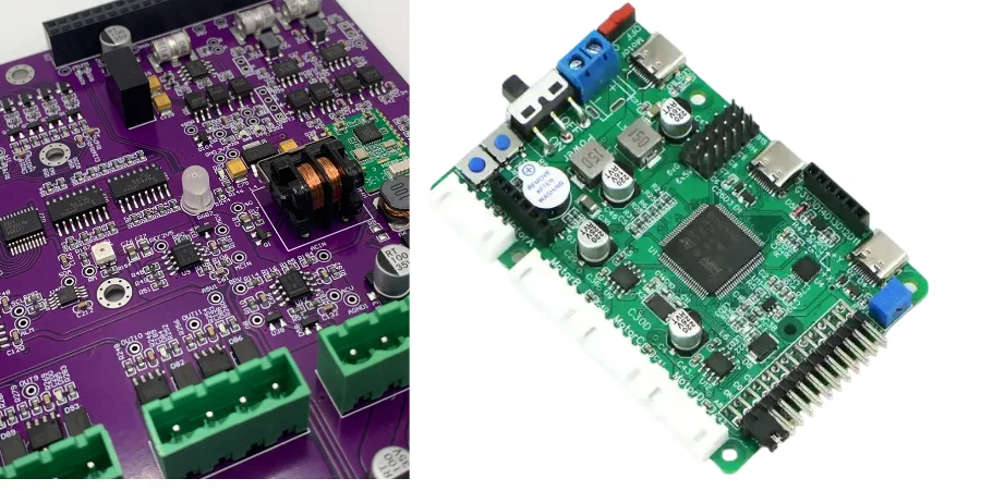
In the Industry 4.0 era, industrial robots are a core pillar of smart manufacturing. The control-system PCB is the robot’s “central nervous system”: it performs real-time computation, drives servo motors, and ensures functional safety. These PCBs often operate in harsh environments with dust, humidity, chemical exposure, and extreme temperatures—where a small failure can stop a production line or even cause safety incidents. Long-term reliability is therefore critical, and Conformal coating is a key line of defense.
From the perspective of a test and certification engineer, this article explains the role of Conformal coating across the full lifecycle of industrial robot control PCBs (especially servo drives and communication interfaces). We go beyond coating materials and connect coating with Design for Testability (DFT), ICT/FCT, CE/EMC certification, and consistency control for volume manufacturing—showing how to build a truly rugged, reliable, and maintainable industrial robot control PCB.
Coating and protection: Conformal coating material selection and process window
The primary job of Conformal coating is to form a strong, uniform protective film over the PCB and components to resist environmental attack. There is no one-size-fits-all solution—choosing the right chemistry and controlling the process window precisely is the prerequisite for success.
1. Strategic selection of coating materials
Different chemistries deliver different protection characteristics, so selection must balance cost, performance, and process complexity.
- Acrylic (AR): The most common choice due to cost effectiveness and ease of application/rework. It provides solid moisture and dust protection and is a good default for general industrial environments. Coating resists humidity and condensation but is not a seal; boards exposed to spray or immersion need a waterproof PCB approach with potting or enclosure sealing.
- Silicone (SR): Best for wide temperature ranges (e.g., -50°C to 200°C). Its flexibility tolerates thermal cycling without cracking and provides excellent moisture resistance.
- Urethane (UR): Known for strong chemical and abrasion resistance. If the PCB may face solvents, fuels, or corrosive chemicals, UR provides better protection, but rework is more difficult. Coating is only one layer of a chemical-resistant PCB strategy; laminate and solder mask choice matter too.
- Parylene: Among the highest-performing coatings, applied via VDP. It forms an ultra-uniform, pinhole-free thin film that can penetrate under components into micro-gaps. However, equipment cost is high and rework is nearly impossible, so it is typically used in aerospace or medical applications.
- Epoxy (ER): Very hard with strong abrasion/chemical resistance. Its hardness also introduces stress risks that can damage sensitive components during thermal cycling, and rework is extremely difficult.
In Servo motor driver PCB best practices, material selection is the first step. For example, high-power servo drives generate substantial heat, so SR with strong thermal stability may be a better choice.
2. Precise control of the process window
After selecting the material, process control determines final Conformal coating quality.
- Application method: Automated selective spraying is the mainstream approach. With programmed paths, it precisely controls coverage and thickness while avoiding areas that must remain uncoated (connectors, test points). Manual spray, dip, and brush are used for small batches or rework.
- Thickness control: The most critical parameter. Too thin reduces protection; too thick increases mechanical stress, hurts heat dissipation, and can crack during cure. Typical thickness is 25–75 μm depending on chemistry and requirements.
- Curing: Different materials require thermal cure, UV cure, or moisture cure. Under-cure reduces performance and may release chemicals that corrode components.
- Masking: Before coating, connectors, test points, potentiometers, and switches must be masked precisely. Any masking mistake can cause poor contact or functional failure—especially in complex EtherCAT interface PCB assembly.
Design for Testability (DFT): keeping test access and diagnosis paths open under coating
Embedding DFT thinking in the PCB design phase reduces downstream manufacturing cost, increases test coverage, and simplifies maintenance. When you introduce Conformal coating, DFT becomes even more important: a poorly considered design can become an untestable “black box” after coating.
1. Test points, interfaces, and diagnostic strategy
- Test point placement: ICT and FCT require physical probe access to test points. Place test points where fixtures can reach them and keep sufficient spacing for probes. Critically, these test points must remain accessible after coating. Common approaches include:
- Test before coating + functional verify after coating: The most common strategy. Run full ICT before coating and then FCT after coating to ensure coating did not introduce issues.
- Permanent masking: Use permanent caps or peelable masking for key diagnostic test points.
- “Window” design: Leave a defined area uncoated as a “test window” at the expense of protection.
- Boundary scan (JTAG/IEEE 1149.1): For complex packages with hidden joints (BGA, QFN), boundary scan may be the only test approach. Its advantage is that it uses the TAP digital interface and is not affected by Conformal coating. For high-speed communication boards such as EtherCAT interface PCB assembly, integrating a JTAG chain is a must-have quality strategy.
- Diagnostic interfaces: Reserve UART, SPI, or I2C debug interfaces and route them to accessible connectors. These interfaces should be masked during coating so they remain usable for deep fault diagnosis when needed.
ICT/FCT testing: validate functionality and reliability before and after coating
ICT and FCT are two key quality gates that play different roles around Conformal coating.
1. Pre-coating ICT: catch manufacturing defects early
ICT is performed after PCBA and before coating. Using a bed-of-nails fixture to contact test points, it quickly detects:
- Shorts and opens: Confirm net connectivity.
- Component values: Measure R/C/L and other passives to ensure they are within spec.
- Orientation/polarity: Check polarity or orientation for diodes, transistors, ICs, etc.
For Servo motor driver PCB mass production, high-coverage ICT is crucial. It catches soldering/placement defects early and prevents defective assemblies from entering the next step (coating), significantly reducing total cost.
2. Post-coating FCT: simulate the real world
FCT simulates the real operating environment and verifies functions against design intent. It is typically performed after Conformal coating as the final outgoing inspection.
- Test scenario: For servo driver PCBs, the FCT setup simulates a host controller (e.g., commands sent via EtherCAT), connects motor loads, supplies power, and monitors outputs like speed, torque, and position feedback.
- Verify coating impact: FCT can verify whether coating introduced negative effects. For example, overly thick coating can hurt heat dissipation and overheat power devices; coating ingress into connectors can break communication.
- Fixture design: FCT fixtures are more complex than ICT. They need electrical connections and may integrate loads, sensors, and communication modules. Fixture stability and durability directly affect Servo motor driver PCB mass production efficiency and test consistency.
A strong EtherCAT interface PCB guide should emphasize that FCT must test not only basic link-up, but also stress cases such as high-throughput traffic and recovery from network interruptions, to ensure robustness in industrial networks.
CE/EMC certification: how coating affects EMC and common mitigation strategies
All electronics sold in the EU must pass CE certification, where EMC is a core requirement. Industrial robot control PCBs combine high-speed digital circuitry and high-power switching circuitry, making EMC particularly challenging. Adding Conformal coating introduces new variables.
1. How conformal coating affects EMC
Coating materials are dielectrics. When they cover PCB surfaces, they slightly change effective dielectric properties between traces and between traces and reference planes.
- Impedance shift: For high-speed lines (e.g., EtherCAT differential pairs), small impedance changes can increase reflection, degrade SI, and worsen EMI behavior.
- Parasitic capacitance: Coating increases surface parasitic capacitance, which can shift filter behavior or change resonance of “antenna-like” structures.
- Thermal effects: Coating can reduce heat dissipation. If power-device temperature rises, electrical behavior can change and alter EMI spectra.
Therefore, EMC testing must use samples processed with the final Conformal coating flow.
2. Common EMC mitigation strategies
When EMC tests fail, corrective actions usually start with PCB design fundamentals.
- PCB stackup: A well-designed Servo motor driver PCB stackup is the foundation of EMC success. Proper placement of signal layers, power layers, and ground planes helps control impedance, reduce crosstalk, and improve shielding. For example, routing high-speed lines as stripline between two ground planes can significantly reduce radiation. Tools such as HILPCB’s impedance calculator help optimize stackups early.
- Grounding and filtering: Ensure a complete low-impedance ground return. Use common-mode chokes, ferrite beads, and capacitors for filtering at power entry and high-speed interfaces.
- Shielding: Metal shielding over noisy sources (switching power) or sensitive circuits (analog front ends) is often effective.
In practice, EMC issues are often multi-factor. HILPCB engineers can support everything from design review to test debugging, helping customers pass CE. Our Multilayer PCB manufacturing experience gives us deep insight into EMC fundamentals.
Dielectric constant comparison of coating materials
| Material | Typical Dk (1MHz) | Impact on high-speed signals |
|---|---|---|
| Acrylic (AR) | 2.5 - 3.5 | Medium impact; suitable for most applications |
| Silicone (SR) | 2.6 - 3.1 | Smaller impact; stable performance |
| Urethane (UR) | 3.0 - 4.5 | Larger impact; evaluate carefully in design |
| Parylene | 2.65 (Type N) | Minimal impact; ideal for high-speed circuits |
Note: dielectric constant varies with frequency. For GHz-class applications, always refer to the detailed datasheet from the material supplier.
Consistency and traceability: protecting Servo motor driver PCB mass production quality
Scaling from prototypes to tens of thousands of units, consistency is the hardest challenge. For Conformal coating, that means every PCB must have the same thickness, adhesion, and protective performance.
1. Automation and process control
- Automation equipment: In Servo motor driver PCB mass production, manual coating is not realistic. Selective coating robots with vision alignment are the only practical path to consistency, repeating the programmed path and flow while minimizing human variation.
- Process parameter monitoring (SPC): Monitor key parameters in real time—coating viscosity, ambient temperature/humidity, nozzle pressure, etc. Statistical process control (SPC) helps detect drift early and prevents large batches of defects.
- Automated Optical Inspection (AOI): After coating and cure, dedicated AOI checks coating quality. UV fluorescence enables fast detection of bubbles, delamination, uneven thickness, and insufficient coverage.
2. End-to-end traceability (Traceability)
In industrial products—especially functional-safety-related components—traceability is essential. When field issues occur, you must trace to the specific lot, equipment, operator, and even component supplier.
- Unique ID: Assign a unique QR code or serial number per PCB.
- Data binding: Bind the ID to all relevant production data, including:
- Component lot numbers
- SMT line/equipment and timestamps
- ICT/FCT results and measurement data
- Conformal coating material lot, equipment parameters, and AOI results
- Database management: Store all data centrally as a “digital twin” record. This supports quality systems (e.g., ISO 9001) and enables root-cause analysis and continuous improvement.
HILPCB’s Turnkey PCBA service integrates MES to provide full traceability reporting from procurement through final test.
Coating rework and lifecycle management
Even with strict controls, rework happens. Conformal coating makes rework more complex, so rework strategy must be planned early as part of Servo motor driver PCB best practices.
- Rework feasibility: Rework difficulty varies widely. Acrylic (AR) can be removed with specific solvents, while Parylene and epoxy (ER) are nearly impossible to remove without damaging the PCB. Selection must balance protection and maintainability.
- Typical rework flow:
- Removal: Use chemical solvents, soldering iron heat, or micro-abrasion tools to remove coating around the failed part.
- Replacement: Remove and replace the failed component.
- Cleaning: Clean thoroughly to remove flux residues.
- Re-coating: Apply localized coating and ensure a smooth seam between old and new coating.
- Re-test: Run full FCT again to confirm full functional recovery.
A robust EtherCAT interface PCB guide should include detailed rework instructions so field technicians can service boards safely and efficiently, minimizing downtime.
Conclusion
Conformal coating is far more than “spraying paint”—it is system engineering for long-term reliability of industrial robot control PCBs in harsh environments. Success requires tight coordination across design, manufacturing, and test.
From selecting the right Servo motor driver PCB stackup to optimize EMC, to enforcing DFT rules for test access; from using ICT/FCT to control quality in Servo motor driver PCB mass production, to building full traceability for complex EtherCAT interface PCB assembly—every decision affects final coating results.
As a trusted partner, HILPCB provides not only high-quality PCB manufacturing and assembly, but also deep expertise in test, certification, and process control to support products across their full lifecycle. We know that a high-quality Conformal coating layer represents your commitment to stability, safety, and reliability.
Common Questions
Why is conformal coating important for industrial robot control PCBs?
Robot control electronics often operate around dust, oil mist, humidity, vibration, and electrical noise for many years. Conformal coating helps protect insulation performance and surface reliability in that harsh industrial environment.
Why must DFT, ICT, and FCT be planned before coating?
Once the board is coated, physical access to test points and debug interfaces becomes more limited. Planning test coverage before coating is the only reliable way to keep manufacturing diagnosis and outgoing validation effective.
How does material choice affect rework and maintenance?
Different coatings create very different service burdens: acrylic is relatively rework-friendly, while parylene and some epoxy systems are much harder to remove safely. The right material therefore depends not only on protection targets but also on lifecycle maintenance needs.
Why is lifecycle manufacturing support important for coated robot-control boards?
Stable production depends on more than one coating step. Manufacturers need traceability, process control, certification awareness, and repair strategy so the same board can be built, tested, serviced, and improved consistently over time.