
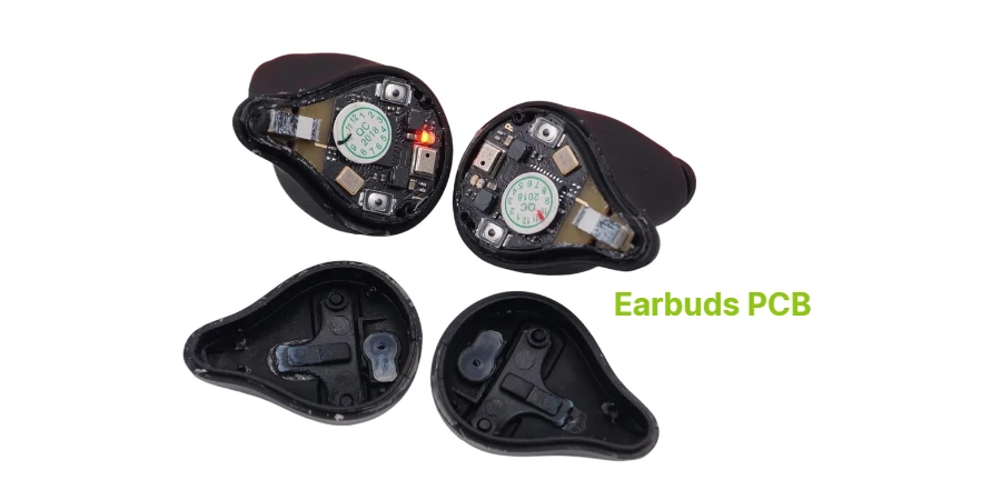
True wireless stereo (TWS) earbuds combine RF, audio, battery, charging and sensor functions in a small product. PCB design balances available volume, antenna keep-outs, acoustic placement, assembly access and testability; it does not alone determine audio quality or battery life.
For fabrication and assembly, provide the released stackup, package dimensions, RF layout and test plan. Confirm rigid-flex construction, fine-pitch assembly and any antenna, battery, acoustic or environmental work against the quoted scope.
Earbuds PCB Structure and Ultra-Miniaturized Design
Earbud PCB dimensions vary widely with the housing, battery location and antenna architecture; there is no universal “under 15 mm × 8 mm” limit for every TWS design. A representative architecture may include:
- A Bluetooth audio SoC or module with the required codec and radio features; the antenna may be on the module, PCB or a separate structure rather than inside the SoC
- Miniaturized audio DACs and amplifiers optimized for In-Ear Earbuds PCB drivers
- Battery protection, power management and charging contacts; wireless charging, where used, commonly belongs to the case and needs its own receiver design
- ANC Earbuds PCB specific: MEMS microphones and DSP for noise cancellation
- Capacitive touch sensors for tap and gesture controls
- Sports Earbuds PCB enhancements: PPG sensors, accelerometers, and sweat-resistant coatings
Compact earbud designs may use multilayer or rigid-flex PCBs; layer count and dielectric construction depend on RF routing, assembly density, yield and mechanical packaging.
Advanced Gaming Earbuds PCB models integrate additional processing for low-latency audio and spatial sound processing, while maintaining the ultra-compact form factors essential for comfortable wear. Over-ear and on-ear designs have more room for drivers and batteries; see our headphones PCB guide.
Specialized Manufacturing for Ultra-Compact Audio Devices
Review the following construction and assembly choices for the actual earbud geometry:
- PCB thickness: Confirm the minimum finished rigid or flexible thickness from stack-up, panel support and yield requirements.
- HDI: Use microvias or buried vias when package escape and routing justify them; agree via structure, lamination sequence and inspection requirements.
- Fine-pitch SMT: Specify the actual metric package dimensions and placement, stencil and inspection capability in the RFQ; very small passives require process qualification.
- RF impedance: Derive trace impedance and tolerance from the antenna matching network and module reference design, not a universal ±3% manufacturing promise.
- Rigid-flex: Define bend shape, stiffeners, copper routing and whether the flex moves during use. A one-time folded interconnect and a dynamic flex have different qualification needs.
- ANC audio paths: Follow microphone port, package cleaning and acoustic placement requirements. Assembly inspection and electrical checks are separate from acoustic calibration.
For SMT assembly, agree stencil, placement and inspection access for the smallest packages and hidden joints. A turnkey assembly request should separately identify enclosure sealing, sensor calibration and RF/audio tests, their fixtures and responsible parties; those services are not established by a bare-board or SMT capability label.
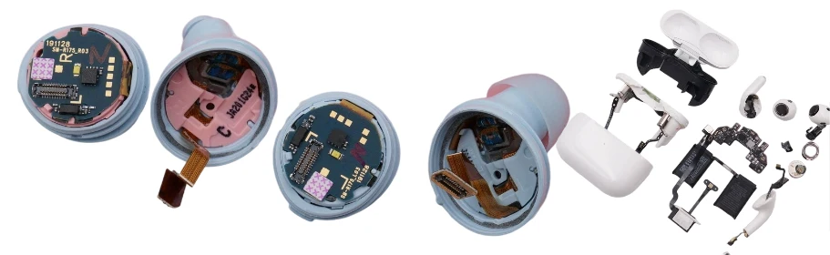
Power Management and Battery Optimization for TWS Applications
TWS Earbuds PCB and Wireless Earbuds PCB designs face unique power management challenges requiring sophisticated battery optimization:
- True Wireless Earbuds Circuit Board: Ultra-low quiescent current designs for extended standby time
- Bluetooth Earbuds PCB: Dynamic power scaling based on audio processing requirements
- ANC Earbuds PCB: Efficient power distribution between audio processing and noise cancellation circuits
- Sports devices: Any physiological sensor or GNSS receiver adds hardware, antenna, calibration and power considerations; these features are not inherent in every sports earbud.
- Gaming audio: Measure end-to-end latency and current in the selected codec, radio and DSP modes; lower latency can change buffering, radio activity and battery demand.
- Charge control and battery protection matched to the cell, contact interface and charging-case architecture
- Evaluate the cell, charger losses and enclosure heat path before considering a thermal PCB construction for the case
TI's TWS charging example distinguishes case and earbud power paths and monitors charging conditions; its circuit is one implementation, not a universal architecture. Measure accessible surface and cell temperatures under charging, playback and fault conditions. Rigid-flex can help package the interconnect, but does not itself improve cooling or establish battery safety.
Earbuds PCB Applications and Market Segments
Earbuds PCB technology serves diverse market segments, each with specific technical requirements:
- TWS Earbuds PCB for Premium Consumer True Wireless Models
- Wireless Earbuds PCB for Fitness and Sports Applications with Health Monitoring
- Bluetooth Earbuds PCB for Budget-Conscious Consumer Markets
- ANC Earbuds PCB for Professional and Travel-Focused Noise Cancellation
- Gaming Earbuds PCB with Ultra-Low Latency and Spatial Audio Processing
- Assistive-listening concepts: Define the intended use and any additional medical-device, acoustic-output and accessibility requirements; a consumer TWS board is not automatically a qualified hearing aid
- Sports Earbuds PCB with Integrated Biometric Sensors and Waterproofing
True Wireless Earbuds Circuit Board applications increasingly include charging case electronics with Miniature Earbuds PCB for case-to-earbud communication and power management. A rigid-flex PCB can help route between constrained regions. Antenna performance still needs evaluation with the actual housing, battery and wearing conditions.
Integrated Ecosystem Solutions for Earbuds Manufacturing
Include the relevant case, component and firmware interfaces in the release package:
Charging Case Electronics:
- TWS Earbuds PCB compatible charging case circuits with wireless charging
- Battery management systems for multi-device charging
- LED status indicators and magnetic sensor integration
- USB-C and wireless charging receiver circuits
Component and antenna integration requirements:
- Antenna geometry, matching components, keepouts and the RF test configuration for the assembled product
- MEMS microphone arrays for ANC Earbuds PCB designs
- Biometric sensors for Sports Earbuds PCB health monitoring
- Haptic feedback modules for Gaming Earbuds PCB immersive experiences
Firmware handoff requirements:
- Approved firmware image and pairing/synchronization acceptance tests
- Supported codec profiles and audio performance limits
- Mobile app compatibility, provisioning and update responsibilities
- ANC configuration, calibration data and programming/version control where applicable
Why Choose HILPCB for Earbuds PCB Manufacturing
HILPCB supports earbuds fabrication and assembly from prototypes through volume, including qualified 0.4 mm substrates, HDI/microvias and 008004 placement, reviewed ±3% RF-impedance options, rigid-flex and precision analog ANC assembly. Available engineering options include antenna optimization, power design, thermal analysis, sealing, sensor calibration, RF/audio/environmental/coating services, and pairing, synchronization, codec, app or ML-ANC integration. Scope depends on the selected package, process qualification, acoustic fixture and system test plan; finished-device latency, ingress and medical/radio compliance require product validation.
Compare the quoted fabrication and assembly route with the actual packages, flex construction and inspection requirements. Request relevant build evidence and agree ownership of radio, acoustic and environmental validation before release.
ISO 9001 is a quality-management-system certification when held by the applicable manufacturing site. IPC-A-610 Class 3 is an assembly acceptability classification, not an independent company certification. Request the relevant certificates and agree inspection class and RF/audio tests for each build.
Common Questions
What are the main technical challenges in TWS Earbuds PCB design and ultra-miniaturization?
TWS earbud development combines antenna clearances, battery safety, EMI management, housing constraints and small-feature assembly. HDI and very small passives may help in some designs. Specify exact package dimensions and qualification requirements rather than relying on ambiguous package codes.
How do you ensure reliable wireless connectivity in ultra-compact Earbuds PCB designs?
Follow the selected radio or module reference layout, antenna keepouts and matching requirements. Check the assembled earbud with its battery, housing and wearing conditions, then measure range, coexistence and synchronization against defined limits. Rigid-flex, shielding and antenna diversity are options when the architecture supports them, not universal requirements.
What specialized manufacturing processes are required for ANC Earbuds and Sports Earbuds PCBs?
ANC earbuds require audio-path calibration and acoustic validation; sports products may require sweat and ingress testing at the assembled-product level. Conformal coating cannot by itself establish an IP67 rating.
What should I evaluate when selecting an Earbuds PCB board supplier for TWS PCB board production?
When evaluating suppliers for an Earbuds PCB board, verify their experience with ultra-miniaturized HDI designs, rigid-flex construction, and wireless module integration. Key evaluation criteria include fine-pitch BGA placement accuracy, antenna design support, battery management testing capability, and waterproofing process quality (IPX rating). Request samples with wireless range testing, current consumption measurements, and audio latency data. For charging-case electronics, define the actual charging interface, battery monitoring and any wireless receiver. A USB-C connector alone does not require USB Power Delivery. Manufacturing location, tooling costs, and production capacity alignment with your forecast volume also affect supplier selection.
Can you manufacture both budget and premium Earbuds PCBs including gaming applications?
Submit the fabrication/assembly data, BOM, quantities and test requirements for the proposed product. Budget, ANC, gaming and sensor-equipped earbuds impose different package, firmware, acoustic and power requirements. Confirm the feasible manufacturing scope and validation responsibilities in the quotation; the PCB fabrication process alone does not establish latency, health-measurement or professional-audio performance.