
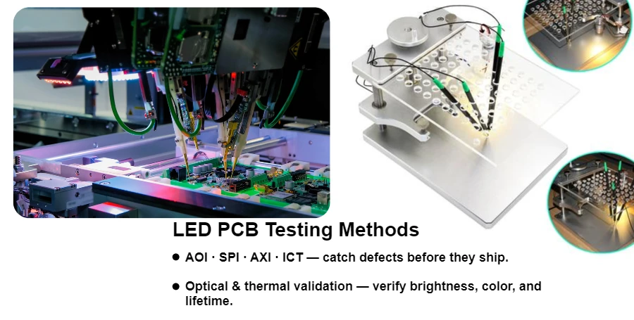
LED testing starts by identifying the delivered item: a bare PCB, a populated LED/driver board, or a complete lamp. Bare-board continuity and insulation checks, assembly inspection, and luminaire optical measurements answer different questions. Define the acceptance limits and test configuration before comparing results or ordering production.
HILPCB supports FR-4 fabrication, metal-core and thermal-board routes, SMT assembly, and turnkey/system integration. Our PCB assembly services connect DFM/DFT review, inspection and the electrical or functional tests defined for the build. The following methods help turn a lighting specification into a practical test plan.
Electrical Testing Protocols for LED Circuit Boards
Use bare-board electrical testing to check specified nets for opens and shorts before assembly. Test the populated board after assembly to evaluate components, driver behavior and LED operation; a bare-board test cannot measure these functions.
In-Circuit Testing (ICT): ICT or flying probe can check accessible nets and selected component values against defined limits. In-circuit parallel paths can affect resistance, capacitance or inductance readings, so define isolation, test access and coverage. Driver switching frequency and output regulation belong in a powered functional test unless the selected ICT platform explicitly supports them.
Functional Testing at Operating Conditions: Verify LED string current, input power, startup, open/short-load response and PWM frequency/duty across the specified supply and dimming range. Include the selected LED forward-voltage range and driver temperature-compensation behavior. Set chamber temperatures from component ratings and the intended application; a fixed −40°C to +85°C profile is not suitable for every lighting board. State whether each test is a design-qualification test, a sampled production check or a test on every released unit.
High-Potential Testing: Where dielectric withstand is required, define the exact test points, AC/DC voltage, ramp, dwell, leakage/trip limit and post-test discharge from the applicable product specification. HILPCB’s box-build test route offers hipot testing up to 3000 VAC between isolated sections when the specified test article and profile support that level, plus insulation-resistance and ground-bond options. A withstand result does not establish adequate creepage or clearance by itself. For metal-core PCBs, review circuit-to-core insulation, hole/edge construction and mounting hardware together; the metal base does not inherently provide protective isolation. Coordinate isolation and heat flow through the high-thermal PCB route.
Thermal Performance Validation
LED junction temperature affects light output, color and reliability. Validate the assembled thermal path with the intended heat sink, TIM, mounting pressure, enclosure, orientation and airflow, rather than comparing loose boards on a bench.
Infrared Thermography: IR imaging can reveal hot spots and compare heat spreading during warm-up. Surface emissivity, reflections, focus and spatial resolution affect the result. HILPCB offers FLIR thermal imaging with 0.1°C camera resolution; resolution is not absolute measurement accuracy. Correlate critical locations with contact measurements. HILPCB offers IR imaging, thermal-resistance evaluation and thermal simulation through its thermal-board services, with the fixture and operating conditions defined for the project.
Thermocouple Measurements: Attach thermocouples at the package manufacturer’s specified solder/case reference point and other critical locations without blocking the optical path. These measure local temperatures, not junction temperature directly. Estimate junction temperature only with the selected package’s thermal model, reference point and matching power definition. Cree LED’s thermal-management note, measurement section explains practical thermocouple and IR limitations. Record ambient temperature and a defined stabilization criterion, then correlate the measurements with the thermal simulation.
Thermal Cycling Tests: Temperature cycling and thermal shock can expose delamination, interconnect fatigue and material-interface failures. HILPCB’s thermal service includes cycling options, including −40↔+125°C programs. Select limits, ramp/transfer, dwell, cycle count, powered state and post-stress electrical/optical checks for the actual materials and components. Cycling is different from steady powered burn-in, and neither alone establishes LED lumen-maintenance life.
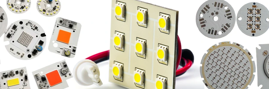
Optical Measurement and Validation
LED optical performance requires specialized measurement equipment and controlled testing environments to ensure consistent light output and color quality.
Luminous Flux and Efficiency Testing
Specify an appropriately calibrated integrating-sphere/spectroradiometer setup and the responsible laboratory when optical measurements are required. Record the tested assembly, drive condition, stabilization and temperature. The measurement package can include:
- Total Luminous Flux: Validates light output meets specifications
- Luminous Efficacy: Confirms lm/W efficiency targets
- Color Temperature: Ensures CCT consistency across production batches
- Color Rendering Index: Verifies CRI meets application requirements
Luminous efficacy needs a stated electrical boundary. For an assumed 1,200lm assembly drawing 10W at the LED-board input, efficacy is 1,200/10 = 120lm/W. If the same measured light output requires 12W at the complete lamp input including its driver, lamp efficacy is 100lm/W. These are calculation examples, not product results; do not use lumens as optical watts when calculating heat generation.
Goniophotometer measurements characterize angular intensity, beam angle and distribution for directional lighting, including automotive lamps. An integrating-sphere result alone does not characterize the beam pattern. DOE’s guide to interpreting optical/electrical reports explains this apparatus distinction; specify the applicable test method and revision for the delivered product.
Color Consistency and Binning
LED color consistency across arrays requires bin selection and measurements under comparable drive and thermal conditions. Select the needed checks:
- Individual LED measurements before assembly
- Post-assembly color uniformity verification
- MacAdam ellipse analysis for color matching
- Spectral power distribution measurements
For RGB and tunable-white assemblies, specify channel-current settings, dimming points, chromaticity targets and calibration storage/readback across the required adjustment range. Compare units after stabilization. A matched incoming bin does not remove color shifts caused by temperature, drive current or the finished optics.
Reliability and Environmental Testing
Choose environmental tests from the use environment and failure risks. Keep design qualification, production screening and long-term lumen-maintenance evidence as separate parts of the release plan.
Highly Accelerated Life Testing (HALT): Temperature and vibration step-stress can help reveal design weaknesses and margins when conducted by a suitably equipped laboratory. Define the stress sequence, functional monitoring and failure-analysis plan. HALT does not convert days of stress into a stated number of service years without a validated failure model. Humidity qualification and production burn-in need their own procedures.
Salt Spray and Corrosion Testing: For outdoor and marine LED applications, ASTM B117 provides a salt-spray exposure method rather than a direct service-life prediction. Define duration, specimen preparation and post-exposure electrical/visual criteria. Evaluate coating coverage, cut edges, connectors and enclosure seals; coating alone does not establish an enclosure IP rating or prevent all ingress into an MCPCB assembly.
Vibration and Mechanical Shock: Automotive and industrial LED applications require resistance to mechanical stress. Specify the vibration spectrum, axes, mounting, duration and powered monitoring from the intended service or customer standard. Inspect LED joints, connectors and heavy components and repeat the defined functional checks after stress.
Manufacturing Process Validation
Use process controls to find assembly defects before powered tests and to investigate drift across production runs. HILPCB’s assembly route can combine printing, placement, reflow and the agreed inspection gates.
Solder Paste Inspection (SPI): Measure deposit height, area, volume and alignment after printing where specified. Trend these results against the stencil/land-pattern process window. For LED thermal pads, coordinate aperture, paste, via condition and reflow profile; paste volume by itself does not determine the completed joint’s thermal resistance.
Automated Optical Inspection (AOI): Check visible component presence, polarity, alignment and solder conditions at the selected process gates. AOI cannot inspect every hidden thermal pad or establish light-output and color performance. Retain first-article orientation references and review ambiguous calls against the agreed workmanship criteria.
X-Ray Inspection: Selected X-ray can reveal solder distribution, bridges and voiding at agreed hidden LED, BGA or QFN locations. Specify the view, void metric, sampling and acceptance limits for the package; projected void area alone is not a complete thermal-performance measurement. A packaged COB module can enter an appropriate assembly route, while bare-die attach and wire bonding require a separately confirmed specialist process and inspection plan.
Quality Documentation and Traceability
HILPCB regularly calibrates test equipment with traceability to national standards; calibration records identify the applicable measurement scope.
Link the released design and BOM to the inspections and tests required for shipment. HILPCB’s assembly quality-record options include first-article evidence, reflow profiles, SPI/AOI summaries, selected X-ray images, programming, ICT/FCT and lot/serial traceability records.
Test Reports and Certificates: Define the order’s report package: revision and unit/lot identity, test method and limits, supply/temperature/fixture configuration, results and disposition. Include certificates of conformance or material records where ordered. SPC can reveal process trends, while product acceptance still uses the specified limits.
Failure Analysis: Preserve failed samples and their original results before rework. Electrical diagnosis, selected X-ray and microsections can help separate assembly, laminate and component causes. If SEM, FTIR, decapsulation or another specialist method is needed, agree the laboratory, sample preparation and destructive-analysis authorization. Record the corrective action and repeat-test evidence rather than treating a repaired sample as proof that every cause is removed.
Data Management: Specify unit versus lot linkage, record format, retention and delivery during quotation. Keep failed results, authorized repair and retest disposition linked to the original identity. Our BOM viewer helps review part data; the LED bin, firmware, thermal setup and test limits still belong in the controlled manufacturing package.
Frequently Asked Questions
What testing is required for automotive LED PCBs?
Separate component qualification from the lighting assembly’s electrical, thermal, EMC and environmental validation. AEC-Q100 concerns integrated circuits; AEC-Q102 concerns optoelectronic semiconductor qualification. Neither is a blanket qualification of the populated PCB or finished automotive lamp. Use the customer’s component and module requirements to define the test plan.
How do you test LED color consistency?
Measure chromaticity against the specified bins/tolerance at controlled current and temperature, then check the assembled array and finished optics where required. For tunable white or RGB, include the defined mixing/dimming points and calibration revision. Identify the optical laboratory and report scope in the quotation.
Can you perform custom testing protocols?
HILPCB supports programming and customer-defined functional testing with the supplied procedure, fixture, firmware and limits. Define any burn-in load, temperature, duration and monitoring, plus qualification or specialist-laboratory work, as separate quoted tasks.
Do you only test LED PCBs?
No. Fabrication and assembly routes also support RF boards, high-speed digital circuits, power supplies, motor controllers, automotive and medical electronics. Select continuity, inspection, impedance or functional tests for the actual design; one LED test sequence does not cover every product.
How do you ensure testing accuracy?
Define the measurand, range, reference, fixture and uncertainty needed for the acceptance limit. Include equipment calibration and relevant measurement-system evidence in the agreed record package. Resolution alone does not establish accuracy, and a near-limit result needs the specified decision rule.
Prepare an LED Manufacturing and Test Inquiry
Send fabrication/drill data, stackup, BOM with LED manufacturer part numbers and bin requirements, placement data, assembly drawings, quantities and sourcing responsibility. Include the driver/firmware revision, supply and dimming range, LED current, thermal reference points, heat sink/TIM/enclosure and intended environment.
Mark the electrical, thermal and optical limits, sample quantities, production-test coverage, fixture ownership, laboratory responsibility and report requirements. HILPCB can coordinate small-batch assembly, repeat production, thermal-board evaluation and box-build integration around that package. The LED manufacturing workflow provides the fabrication/assembly context; a defined first article and test record package makes the next production decision reviewable. HILPCB can scope optical and metrology services such as a 2 m integrating sphere, goniometry, spectral/color calibration, and FLIR thermal imaging, together with custom fixture and test development. Failure-analysis options include cross-sectioning, SEM and FTIR; calibration, measurement-system R&R, a customer quality portal, and full traceable reports can be defined by project. Identify the provider, test article and acceptance conditions in the quote; component measurements do not qualify a complete luminaire or establish safety by themselves.