
Select an NTC inrush-current limiter only after defining the charging path, operating conditions, and restart behavior. Then check the exact part’s cold resistance, capacitive-load or energy ratings, continuous-current derating, and thermal recovery against that circuit. Validate the result with measured current, voltage, and temperature waveforms—including short interruptions and bypass faults.
An NTC may be a practical way to reduce startup current, but it is not a guarantee of a limited peak on every restart. If the available resistance after a hot interruption is insufficient, consider a controlled precharge method, a managed restart strategy, or another architecture rather than relying on a cold-start calculation.
First, define the job the NTC must do
An inrush-limiting NTC thermistor is placed in a charging path. Its resistance is relatively high when its body is cool. Current heats the device, reducing its resistance. Its voltage drop and dissipation depend on the actual current and operating state.
That makes it different from three other functions:
- Temperature sensing: A sensing NTC is selected and calibrated to infer temperature, often in a divider. An inrush NTC is selected for its ability to handle current and transient stress.
- Current regulation: An NTC does not actively hold current at a commanded value. Its resistance changes with temperature, current, and time.
- External surge immunity: Startup inrush is current drawn by the equipment. External surges are disturbances entering it. An NTC does not replace the required surge-protection and overcurrent-protection design.
Map the actual current paths before choosing a part. Depending on the design, a limiter may be placed on an AC side or in a rectified path. What matters is whether the intended charging current passes through it and how that location affects the rectifier, bypass, protective devices, and fault paths.
Start with the bus and its operating states
Document the input range, AC or DC source, source and wiring impedance, rectifier arrangement, total effective input capacitance, load behavior during charging, and expected startup and interruption frequency. Include capacitance tolerance, capacitor ESR, and any other charging path that can bypass the NTC.
Then define at least these states:
- Cold start: The limiter has settled near its initial ambient temperature.
- Operating state: Continuous current and the enclosure determine its hot temperature.
- Short interruption: Input power returns before the limiter has cooled fully.
- Residual-charge restart: The bus retains some voltage when power returns.
- Bypass operation: A relay or other switch may short the limiter after charging.
- Faulted operation: The NTC, bypass, controller, or protection may not behave as intended.
These states interact. For example, a hot NTC may provide little initial resistance, while a partly charged bus may reduce—or, depending on the source and topology, alter—the voltage driving the next charging event. Test credible combinations rather than assuming every restart begins with an empty capacitor and a cool limiter.
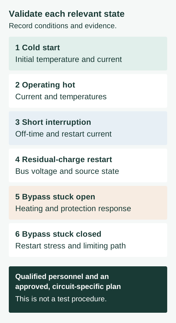
| State | Evidence to consider |
|---|---|
| Cold start | Initial temperature, current and bus voltage |
| Operating hot | Current, body and nearby temperatures |
| Short interruption | Off-time, thermal history and restart current |
| Residual-charge restart | Bus voltage, source state and current waveform |
| Bypass stuck open | Sustained current, heating and protection response |
| Bypass stuck closed | Restart stress and loss of the limiting path |
Use a circuit-specific, approved plan and qualified personnel; this table is not a live-test procedure.
Interpret R25 before estimating current
R25 is nominal zero-power resistance at 25°C. It is not necessarily the resistance immediately before switching. Actual initial resistance depends on the body temperature and part tolerance; after an interruption, it also depends on the preceding operating history and cooling environment.
For a simplified initial-current estimate, assume an ideal constant-voltage source, an initially uncharged capacitor, no other circuit effects, and an NTC whose resistance remains fixed at its initial value. For that model, the current at t = 0 is:
This is the initial current of the stated model, not an established upper or lower bound for the real circuit. Source impedance, AC switching phase, initial capacitor voltage, rectifier behavior, resistance tolerance, and NTC self-heating affect the waveform. Because resistance changes during the event, even the time of the real peak needs verification.
The estimate can help explain and screen the assumed model. Do not use it to set ratings for the limiter, rectifier, relay, fuse, or instruments. Actual conditions need validation through an applicable transient analysis and measured waveforms.
Read a candidate’s exact datasheet—not just its resistance
Check the manufacturer’s applicable resistance tolerance, continuous-current derating, energy or capacitive-load ratings and their test conditions. These are separate checks and do not by themselves approve a device for an arbitrary bus, charging circuit, repetition pattern or enclosure.
Retain the exact manufacturer, complete part number, datasheet revision and any written clarifications with the design record. Resolve conflicting versions with the manufacturer before qualification. A different device with the same nominal R25 is not automatically an equivalent replacement.
Example: reading one TDK S237 row
The TDK Electronics/EPCOS S237 data sheet, dated 2026-05-19, version b, lists the electrical row B57237S0100M0**. This example shows how one manufacturer reports its conditions; it is not a selection recommendation.
| Entry | Value and condition |
|---|---|
| R25 and resistance tolerance | 10 Ω nominal; ±20% tolerance |
| Imax | 3.7 A only at ambient 0 to 25°C |
| Ctest | 700 µF at 230 VAC or 2800 µF at 110 VAC |
| Rmin | 0.223 Ω at Imax and 25°C |
| Thermal cooling time constant | Approximately 90 seconds in air |
The sheet’s maximum permissible capacitance test specifies ambient 25 ±5°C, capacitance equal to Ctest, and 1000 cycles. The capacitance entries are not a joule rating and do not prove suitability for an actual circuit.
The sheet supplies no above-25°C current derating curve or formula. Seek applicable manufacturer guidance for those conditions; do not infer an allowable current from thermal constants or Pmax. The cooling time constant is not a full-cooldown time.
The ** characters denote manufacturer delivery suffixes, not one complete ordering code. Confirm the complete code and the current document version for a real purchase.
Check capacitance and energy as separate questions
The energy stored in a capacitor at voltage V is:
This describes capacitor stored energy at that voltage. It is not automatically the energy dissipated in the NTC. During charging, energy is distributed among the source, limiter, wiring, rectifier, capacitor ESR, and other parts of the circuit. Initial bus voltage and the source waveform also matter.
A useful circuit-specific NTC dissipation calculation integrates its instantaneous voltage and current over the event. Compare that result, and the relevant waveform and repetition conditions, with the manufacturer’s applicable rating—not merely with the capacitor’s final stored energy.
Similarly, a manufacturer’s maximum capacitive-load rating is meaningful only with its associated test conditions. It is not automatically equivalent to another manufacturer’s energy rating. Manufacturers may use different test circuits and initial conditions. Verify the applicable rating conditions for the exact device and do not assume that a catalog test duplicates the finished PCB’s charging path.
Account for repeated starts as well as one event. A part that handles an isolated cold pulse may encounter a different initial temperature and resistance on the next pulse.
Check continuous current and the installed thermal environment
The NTC must also tolerate the actual current that flows after startup, unless the circuit reliably bypasses it—and the stuck-open bypass case has been assessed.
Use the selected manufacturer’s continuous-current rating and applicable temperature-derating guidance for the device and revision. If the published guidance does not cover the intended conditions, seek clarification rather than inventing a derating rule. Check the real current waveform, not only a nominal load label. Resistance at operating current is useful for estimating loss, but the final body temperature depends on more than the calculation:
- Ambient temperature and airflow
- Lead length, copper, solder joints, and mounting
- Nearby heat-producing components
- Enclosure, orientation, and contamination exposure
- Current waveform and bypass state
An NTC can be hot enough to affect adjacent components even when it remains within its own specified operating conditions. Review the PCB, wiring, connectors, and enclosure materials as a system.
Treat hot restart as a separate design decision
After power removal, the NTC cools and its resistance recovers. A short outage may leave it much hotter—and at lower resistance—than it was for a cold start. The bus may also retain charge, while the controller and bypass can change state at different rates.
A datasheet thermal time constant is not a promise of full cooling or recovery to R25 after one time constant. It describes thermal response under the manufacturer’s conditions; the installed assembly can behave differently. There is no universal restart time.
Establish whether the design can tolerate the resulting current for the credible interruption durations and thermal histories. If not, decide how the product will manage restart or use a different limiting approach. A power-cycle policy is only useful if the control and power architecture can enforce it under the faults and resets being considered.
Design the bypass as a state machine, not a promise
A bypass can reduce NTC dissipation after the bus has charged. Bourns illustrates a delayed relay bypass, but its timing belongs to that circuit; it is not a general delay for other products.
Define what must be true before closure in the actual design. A timer alone may not prove that the bus charged: low input voltage, load demand, a fault, or a controller reset may change the result. Consider how the bypass opens on interruption, how the controller restarts, and whether contact feedback is available. Feedback can help detect a state; it does not by itself prove that precharge was adequate.
A relay is not automatically fail-safe. Contacts can fail open or weld closed, and a controller can command closure too early. Coordinate the contact’s make, carry, and break ratings with the actual AC or DC load and waveform. Panasonic’s relay cautions discuss contact damage and welding under unsuitable conditions.
Failure-state-to-evidence table
The required outcome is design-specific. For each row, record the consequence, protective response, and evidence needed to justify it.
| State or fault | Design question | Evidence to hand off |
|---|---|---|
| Bypass stuck open | Can the NTC and surrounding assembly withstand continuing current and heat? | Current waveform, installed temperatures, derating review, and protection response |
| Bypass stuck closed | What limits the next charging event without the NTC? | Worst credible restart waveform and contact, rectifier, capacitor, and fuse stress review |
| Bypass closes early | Can substantial charging current transfer to the contacts? | Closure criteria, bus/current waveforms, and contact make-rating assessment |
| Controller reset or supply dip | Does the bypass return to the intended state, including during a short interruption? | State-transition analysis and interruption/reset test records |
| NTC open | Is power lost as intended, or can another path energize the bus? | Fault-path review and observed protection/control behavior |
| NTC short | Is inrush limiting lost, and what carries the resulting pulse? | Faulted startup waveform and downstream stress/coordination analysis |
| High-resistance or degraded path | Can inadequate charging or localized heating create another hazard? | Voltage drop, temperature observations, and relevant component inspection criteria |
| Repeated hot restart | Does recovered resistance remain adequate for the permitted restart sequence? | Off-time, residual bus charge, NTC temperature or resistance, and current records |
Include the input fuse or other overcurrent protection, rectifier, connectors, and switching contacts in the coordination review. Compare their voltage, current, interrupting, pulse, and repetition ratings—as applicable—with the actual circuit stresses and protective clearing behavior. A fuse rating alone does not establish that every upstream and downstream component survives every inrush or fault waveform.
Validation handoff checklist
Power-input tests require qualified personnel and an approved plan for the actual circuit. Engineering review must define isolation, safe discharge and verification thresholds, instrument earth and common-mode connections, voltage, current and CAT ratings, and emergency and fault-test controls. Account for all supply and battery paths, stored energy and the actual measurement setup.
Hand off the following before design approval:
- Configuration: schematic and PCB revision, limiter manufacturer and part number, datasheet revision, substitutions, and manufacturer clarifications.
- Input and loading: input extremes, relevant source impedance, capacitance tolerance, load behavior, and credible AC switching phases or DC input conditions.
- Initial conditions: cold and hot limiter states, residual bus charge, and short interruptions varied across credible combinations.
- Waveforms: measured input current, bus voltage, and relevant bypass/control signals, with instrument ratings and setup recorded.
- Thermal conditions: ambient extremes, representative enclosure and airflow, operating current, NTC body and leads, PCB, and nearby components.
- Faults and coordination: the table’s bypass, controller, and NTC states; contact, fuse, rectifier, capacitor, and connection stresses.
- Disposition: results compared with the exact applicable ratings and the project’s approved criteria; unresolved conditions assigned for engineering review.
For the wider supply design, see the PCB power-integrity checklist.
HILPCB supports PCB manufacturing and PCB assembly (PCBA), including surface-mount and through-hole assembly. To request a quote, provide the released fabrication files, BOM with complete manufacturer part numbers for the NTC and other components, assembly drawing, placement data, quantity, sourcing responsibilities, and the requested inspection and test scope. Confirm the assembly and test requirements for the specific project during quotation. The design team remains responsible for the power-input design, component ratings, safety, and circuit validation.
FAQ
Is R25 the NTC resistance at every cold start?
No. R25 is nominal zero-power resistance at 25°C. Actual initial resistance also depends on body temperature and tolerance.
Can capacitor energy be used directly as the NTC energy rating?
No. Capacitor stored energy and NTC dissipated energy are different quantities. The charging path and manufacturer’s rating conditions determine the appropriate comparison.
Does bypassing the NTC solve hot restart?
Not necessarily. A hot limiter may still have low resistance when power returns, and the bypass may be closed, welded, or commanded incorrectly. Evaluate the complete restart and fault sequence.
How long must an NTC cool before restarting?
There is no universal time. Recovery depends on the part, preceding current, ambient, mounting, airflow, enclosure, and required resistance. A thermal time constant is not full-cooling time.
Can an NTC replace a fuse or surge protector?
No. Inrush limiting, overcurrent protection, and external surge immunity address different conditions. Each function requires analysis and coordination in the actual input design.