
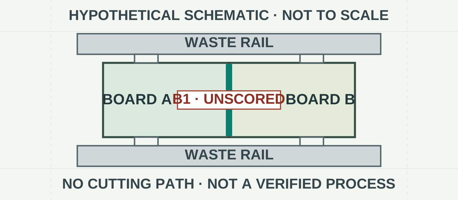
Jump scoring, also called skip or interrupted V-scoring, leaves selected sections of a score path unscored. It is worth considering when a straight scored boundary is useful but a continuously scored panel may not provide the desired handling support. The decision is incomplete, however, until every retained bridge has a feasible removal method and the populated panel has been assessed through the intended process.
Choose continuous V-score when a full straight score path, panel handling, and separator access are compatible. Consider routed tabs when outlines are irregular, score stops cannot be made as required, or final separation favors routing. A combination or a carrier may be appropriate when no single method works.
For broader panel layout considerations, start with HILPCB’s panelization design guide. This article adds the details needed to specify score stops, retained connections, and their eventual release.
First, distinguish the material that remains
Three features can look similar on a panel drawing but have different jobs:
- Scored web: Laminate remaining between score grooves. Its thickness affects panel retention and the subsequent separation operation.
- Unscored bridge: A deliberately retained section along an interrupted score path. It remains a connection until a later operation removes it.
- Waste rail: Material outside the finished boards used for handling, tooling, or support. It may contain scored, partially scored, and unscored regions.
There may also be a transition or runout zone between a full-depth score and an unscored area. Depending on the scoring equipment and process, the groove can become progressively shallower rather than ending abruptly.
Equipment can support continuous or segmented grooves, but the available process depends on the selected fabricator and does not by itself prove panel strength.
Adding bridges or leaving a thicker scored web may help retain an array, but either change can also make separation more difficult. Its effect depends on the panel geometry, material, support, and cutting method.
Select the separation system
| Candidate | Starting point | Questions to resolve |
|---|---|---|
| Continuous V-score | Straight boundaries where scoring across the full path is acceptable. | Will the panel remain adequately supported through fabrication, shipping, assembly, and test? Can the separator reach every line? |
| Interrupted V-score | Straight boundaries where selected areas must remain unscored. | Can the fabricator achieve the required full-score extents and protected zones? How will every bridge be removed? |
| Routed tabs | Irregular outlines, selective connections, or cases where scoring or scored-edge separation is unsuitable. | Are tab placement, strength, tool access, debris control, and final edge quality acceptable? |
| Combination | Different boundaries have different needs. | Do score and route features intersect safely, and does the complete release sequence work? |
| Carrier or individual boards | The array cannot satisfy handling or separation needs as designed. | Can the alternative support the boards throughout assembly and test without obstructing components or processes? |
Use the table as a screening tool, not a ranking of stress performance. A wheel separator, supported router, saw, shear, or controlled break can produce different results depending on the actual board and fixture. Manual breaking of either scored webs or perforated tabs should not be assumed safe for a populated design.
Material matters too. Confirm the proposed separation method for the actual laminate and stack-up.
Define the score path as a controlled feature
A short line on a drawing is not enough to define a stop score. It may not tell the fabricator whether the line marks the required full-depth extent, the beginning of blade lift, or the end of any permitted transition.
For each score path, use a common panel datum, units, orientation, and revision to specify:
- Path ID and centerline: Identify the line, direction, connected board edges, and associated rails.
- Required full-depth extent: State where the score must meet the agreed groove and remaining-web requirements.
- Permitted transition zones: Define where a partial-depth groove is allowed between a full score and a protected region.
- Protected no-score regions: Identify areas that must remain unscored on the specified faces, including the minimum retained region of each bridge.
- Groove and web requirements: Agree the nominal geometry, top- and bottom-face requirements, remaining-web target, tolerances, and measurement method with the fabricator.
- Related routing: Identify outlines, slots, tabs, perforations, and score–route intersections. State which feature controls where they meet.
- Final release: Link each bridge or tab to a tool, fixture support, removal order, and verification owner.
Specify the required functional boundaries rather than guessing an exact blade-lift command. The fabricator should confirm whether its proposed process can make the requested score, transition, and protected regions. The assembler should separately confirm that the resulting panel can be held and separated.
Keep the marked-up drawing consistent with the manufacturing data. The CAM files guide can help organize that handoff; it does not replace a feature-specific stop-score drawing.
Use a score-path-to-release matrix
Attach a matrix to the panel drawing so that a retained connection cannot be overlooked between fabrication and assembly.
Decision gate: Continuous score → interrupted score → routed tabs or combination → carrier or individual boards.
Record the reason for moving past each option and the unresolved risk. This is a review sequence, not a mandatory manufacturing sequence.
| ID | Method and path | Full-score extent | Transition / protected zone | Retained connection | Removal tool, support, and order | Verification / owner |
|---|---|---|---|---|---|---|
| S1 | Enter path and board references | Enter coordinates or drawing zones | Enter agreed zones | Enter bridge and rail IDs | Enter planned method and sequence | Enter measurement, criterion, and owner |
| T1 | Enter routed-tab reference | Not applicable | Enter route and edge requirements | Enter tab ID | Enter planned method and sequence | Enter measurement, criterion, and owner |
A useful completeness check is to trace every physical connection from the delivered panel to a finished board. If a bridge, tab, scored web, or rail connection has no removal operation, the release plan is unfinished.
Hypothetical example: one interrupted boundary
The following dimensions and acceptance values are invented for illustration only. They are not HILPCB specifications, verified capabilities, equipment clearances, or recommended production limits.
Assume a panel drawing uses millimeters, with its origin at the lower-left corner:
- Two hypothetical boards sit side by side. Their common separation path S1 lies at
x = 50, fromy = 10toy = 90. - Waste rails occupy the regions below
y = 10and abovey = 90. Routed boundaries leave four separately identified rail tabs, T1–T4, two per board. - The nominal board thickness is 1.60 mm. For this example only, the proposed remaining-web target on fully scored portions is 0.40 ± 0.05 mm, measured by an agreed method.
- Full-depth scoring is required along S1 from
y = 12–42andy = 58–88. - Partial-score transitions are permitted from
y = 10–12,42–45,55–58, and88–90. - Bridge B1, from
y = 45–55, must remain unscored on both faces after fabrication.
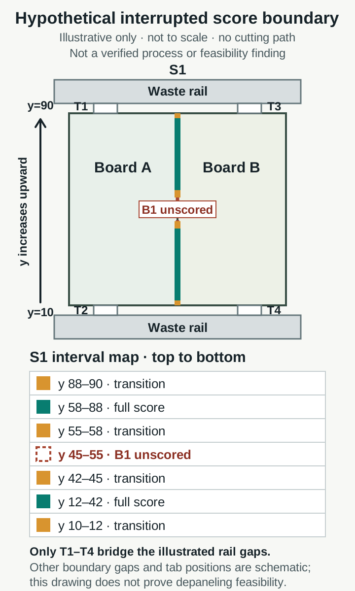
Illustrative only: not to scale, not a cutting path, and not a verified manufacturing or depaneling process. T1–T4 locations and all other boundary gaps are schematic; the drawing does not establish depaneling feasibility.
The drawing would also specify groove geometry, measurement locations, top/bottom registration, routed edges, tab geometry, and the permissible condition of the rail regions. For brevity, those values are not invented here. The fabricator must assess whether the illustrated zones are feasible; the example makes no claim that they are.
A proposed release sequence is not ready for approval until project-specific verification covers the exact tool path, cutter diameter and compensation, finished-edge allowance, fixture support before and after every removed connection, component clearance, debris control, T1–T4 removal order, and final inspection of edges, dimensions, components, and solder joints. B1 is on the shared separation path; routing removes material, so a centerline alone does not prove both final outlines. Once these items are verified, the sequence may proceed to project-specific approval. Manufacturing and assembly engineering must approve the actual sequence before release.
Plan assembly handling before approving the panel
A panel can survive fabrication and still be unsuitable for assembly. Review the intended populated configuration with the assembler, including:
- Conveyor direction, rail contact surfaces, and panel orientation.
- Fiducials, tooling holes, clamps, and support locations.
- Components or connectors that overhang the board or obstruct a separator.
- Panel support during printing, placement, soldering, inspection, and test.
- Handling and transport between operations, including after partial separation.
- Contact points and keep-out areas for every depaneling fixture.
Panel-level fiducials should remain available for the operations that need them. See the PCB fiducial marks guide when preparing the placement and tooling drawing.
Pay particular attention to fragile components near the eventual separation path. Consider board bending, component orientation and local geometry when evaluating the actual assembly.
Verify the actual release sequence
Agree on first-article checks before production. The sampling, measurements, and pass/fail criteria should be specific to the product and approved by the responsible parties.
Bare-panel checks
Compare the delivered panel with the approved revision. Inspect both faces for score alignment, full-depth extents, transitions, protected areas, bridge integrity, and rail connections. Measure representative remaining web using the agreed method and locations. Check routed outlines, tabs, and score–route intersections against the drawing.
A visual check alone may not establish remaining-web thickness. Likewise, a satisfactory web measurement at one location does not prove that every stop or bridge is correct.
Representative assembly and separation
Run a populated or otherwise representative panel through the actual planned handling and depaneling sequence. Record the tool, program, fixture, support points, operator instructions, and cut order. Check what supports the array after each connection is removed, not just before the first cut.
Inspect finished board dimensions and edges, including burrs, exposed fibers, cracking, or delamination as relevant to the agreed criteria. Inspect components and solder joints; add electrical, functional, or other tests where the product’s failure modes justify them.
Record the agreed inspections and results in the PCB assembly inspection report, including any issues found after separation and their disposition.
Where flexure risk warrants it, measure strain and strain rate at selected sensitive locations during representative operations. IPC and JEDEC’s IPC/JEDEC-9704A Printed Circuit Assembly Strain Gage Test Guideline describes a strain-gage methodology; its public scope notes that limits can come from the customer, component supplier, or internal practice. It does not establish a universal jump-score strain limit.
RFQ checklist and approval gates
For a quotation request, provide enough information for feasibility review without treating the quote as design or qualification approval:
- Board fabrication data, stack-up, material, thickness, quantity, and required delivery format.
- Panel drawing with datum, revision, orientation, rails, tooling, and finished board outlines.
- Score-path IDs, full-score extents, permitted transitions, protected regions, and bridge IDs.
- Proposed groove geometry, remaining-web requirements, tolerances, and inspection method—or a request to agree them.
- Routing, tab and perforation details, plus intended finished-edge requirements.
- Assembly constraints, component envelopes, handling direction, and proposed depaneling tools and sequence.
- Applicable contractual standards, revisions, class, and product-specific acceptance criteria.
- Open questions about feasibility, alternatives, first articles, and who approves changes.
Keep the gates separate:
- Quotation: Obtain a response on price, lead time, assumptions, and proposed feasibility.
- Design release: Resolve drawing and manufacturing-data questions with the fabricator and assembler; approve the controlled revision.
- Product qualification: Verify representative panels, assembly handling, and final separation against the product owner’s agreed criteria.
A quotation or drawing review alone does not qualify the finished assembly. For a project involving both fabrication and assembly, include the panel and separation requirements when discussing PCB assembly services. For unresolved project-specific questions, contact HILPCB before releasing the panel design.
FAQ
Is jump scoring the same as skip scoring?
The terms are commonly used for an interrupted V-score path that leaves selected material unscored. Define the actual scored, transition, and protected regions rather than relying on the name alone.
Can a wheel separator cut an unscored bridge?
Do not assume it can. Identify a suitable bridge-removal operation and verify that the fixture supports the panel before and after that operation.
Does an unscored bridge guarantee a stronger panel?
No. It may contribute to retention, but the result depends on the bridge, surrounding geometry, material, and loading. Verify handling with a representative panel.
When should routed tabs replace interrupted scoring?
Consider tabs when the outline is irregular, required score stops are infeasible, or the planned separator cannot safely release the panel. Verify tab removal, support, debris, and finished-edge quality.
What should the fabricator and assembler approve?
The fabricator should confirm the manufacturability of the controlled score and route features. The assembler should confirm handling and tool access. The product owner should approve the verification plan and qualification criteria.