

A failed production test or obsolete component creates two separate decisions: how to recover the affected assemblies, and what to change before the next build. A controlled modification can preserve useful inventory and tooling when the fault is well understood. A new fabrication revision is usually the better route when the fix changes internal copper, component footprints or the circuit architecture.
Consider an illustrative emissions failure. A temporary filter change may help locate the noise source on a test unit. Turning that experiment into production requires an approved circuit change, a reproducible assembly method and repeat emissions testing. The successful bench fix is evidence for the next step, rather than the complete release decision.
HILPCB's PCB design service covers legacy-board respins, EOL component changes, EMC/thermal redesign and manufacturing review. It connects the design change to fabrication and assembly, which is useful when the eventual deliverable is a repeatable new revision rather than a one-off patched board.
PCB Modifications: What Can Be Reworked and What Requires Redesign?
Component Obsolescence Modifications
Compare operating limits, pin functions, package, footprint, startup behavior, firmware and qualification needs before approving an alternate. A matching package or nominal voltage is only part of that comparison.
Typical routes include:
- Pin-compatible substitution: An existing footprint may be usable after electrical and firmware checks. Confirm the exact ordering code and approved source in the BOM.
- Multi-source options: HILPCB’s substitution-engineering database covers more than 50,000 parts. Qualify each alternate and any support-component or firmware variant, and link procurement approval to the correct assembly revision.
- BGA-to-QFN conversion: A package change normally needs a new footprint, escape routing and possibly a different circuit. Treat it as a layout revision, not routine replacement on the same pads.
- Through-hole-to-SMT migration: Revise footprints, mechanical support and soldering requirements together. Check whether the enclosure and test access can be retained.
EMI/EMC Modifications
HILPCB can perform root-cause review using AOI/ICT findings and rework analysis. Use the failure report, test configuration and frequency content to locate likely sources and coupling paths. A filter or shield that helps one frequency can affect power integrity, signal edges or another operating mode, so document the experiment and repeat relevant measurements.
Possible changes and their production implications:
- Filter insertion: Existing resistor links or optional footprints can support a controlled component change. An unplanned trace cut and added wire need their own approved workmanship and retention method.
- Ground stitching: Populating an existing ground connection can be an assembly change. Adding plated vias or changing an internal plane requires a fabrication revision.
- Crystal-circuit layout: Placement, return paths and component values should follow the device guidance. Adding a guard ring to the production artwork is a layout change, not a guaranteed emissions remedy.
- Differential routing: Rerouting can address an identified imbalance or discontinuity, but a new route must be checked against the interface's channel requirements. HILPCB offers ±5% field-solver/TDR review options for eligible controlled-impedance changes; a hand patch does not recreate a production-controlled trace.
Production Yield Modifications
Separate a design problem from an assembly-process or component problem using SPI/AOI findings, soldering profiles, test logs and defect locations. Then change the part of the process that caused the defect.
Examples:
- Thermal-relief adjustment: Changes to copper connections belong in the next board artwork and need electrical/thermal review.
- Pad optimization for tombstoning: Review pad geometry together with paste volume, component placement and heating balance; a footprint change affects future boards.
- Via-in-pad filling: Specify the intended fill and cap construction for a new fabrication lot. It is not a general repair that can be added to every populated BGA board.
- Stencil-aperture adjustment: A revised stencil can change paste deposition without changing board copper. Verify paste volume and solder-joint results on a pilot build.
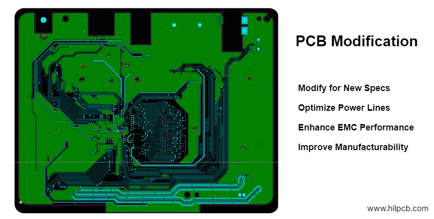
Documented PCB Modification Workflow
1. Establish the Fault and Choose a Route
- Identify the affected board/assembly revision, quantities and reproducible failure condition.
- Compare controlled rework of existing units, a process correction and a new fabrication revision.
- Check parts, native files, access, thermal history and any limits on modifying the assembly.
- HILPCB offers same-day, two-hour feasibility review for eligible urgent requests; this assessment is separate from repair implementation and does not guarantee a fix. Agree scope, schedule assumptions and approval owner before work starts.
2. Release a Controlled Change Package
- Record the schematic/BOM/layout changes or the authorized rework instruction, with before/after identification.
- Run applicable ERC/DRC, stackup, footprint and DFM/DFA checks; assess signal and power effects where relevant.
- For a new revision, release matched fabrication, drill, BOM, placement and assembly files.
- Define inspection, functional test, compliance retesting and the disposition of remaining old inventory. The scoped HILPCB engineering handoff can include engineering CAD, ERC/DRC results, modification documentation, Gerber generation/verification and one customer revision round.
3. Build, Verify and Approve the Result
- Confirm material, component, tooling and test-fixture availability before committing the build schedule. For eligible approved targeted fixes, HILPCB’s 24–48-hour implementation milestone begins after files, parts, change approval and route readiness; it is not the same-day two-hour feasibility review.
- Build the agreed validation quantity and inspect the changed features. Physical-sample X-ray, delayering and optical reconstruction are separately scoped analysis services that can take 24–48 hours.
- Run the defined electrical, functional and any affected environmental/compliance tests.
- Record the result and customer approval, then release the repeatable method or new revision for production. Eligible routes can include dedicated fast fabrication, priority assembly, FCT and overnight shipping; schedule depends on parts, approvals and capacity.
For physical rework, the applicable contract and approved procedure determine the permitted method and acceptance. The publisher's IPC-7711/21 overview describes procedures for repair, rework and modification; citing the guide does not by itself approve a particular product change.
PCB Modification Cost Drivers
Compare the complete route, not just the charge for editing a few nets:
- Engineering: Root-cause work, available source files, circuit/firmware changes, mechanical constraints and review effort. Published reference engineering fees were $500–800 for up to 10 net changes, $800–1,500 for 10–50, and $1,500–3,000 for more than 50; confirm current written pricing. The historical emergency option was a 24-hour service at a 50% surcharge, with the engineering fee credited toward redesign if repair failed; these are reference terms, not a current fixed tariff.
- Tooling and setup: Revised stencil, fixtures, programming, special handling and work instructions.
- Unit work: Components, board fabrication or physical rework labor, inspection and test time. HILPCB accepts prototype orders without a minimum order quantity; 5–50 units is a typical pilot quantity, not a minimum.
- Validation and inventory: Pilot samples, external retesting, potentially unusable parts and the disposition of existing boards.
Illustrative cost calculation: Assume a proposed route has $300 of fixed engineering/setup cost and $12 of incremental work per unit. At 20 units, the allocated cost is $300 ÷ 20 + $12 = $27 per unit; at 100 units it is $15 per unit. These are hypothetical inputs, not HILPCB prices. Compare that result with a quoted new-revision build, including validation and inventory exposure. A lower patch cost can lose its advantage when every unit needs lengthy manual work or additional testing.
For HILPCB design work, the scoped handoff can include unlocked native CAD and manufacturing files. Specify the required revision history, approved BOM/alternates, assembly or rework drawing and test records in the quotation, so both parties price the same release package.
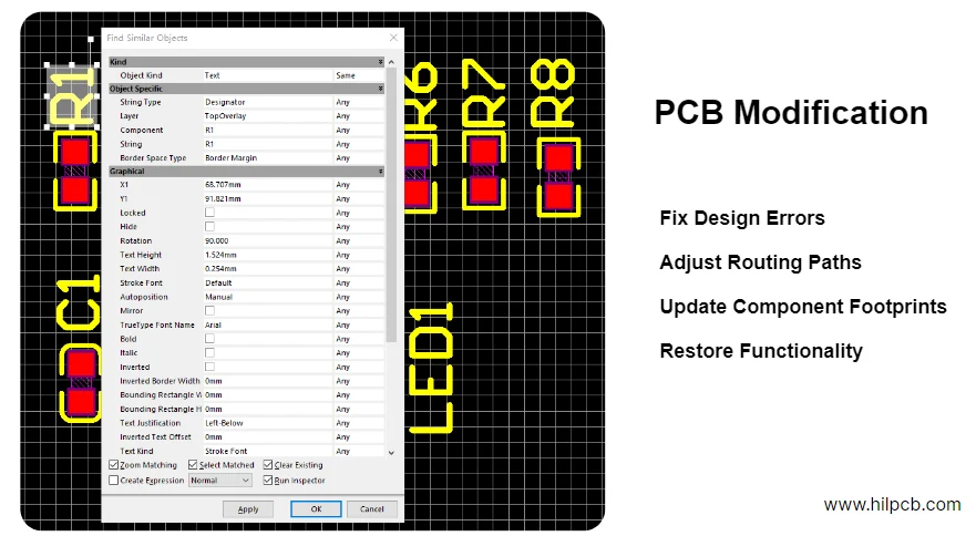
When PCB Modification Beats a Larger Redesign
A constrained modification is a useful candidate when:
- The fault is localized: Its cause and the affected functions are understood; the area or number of changed nets alone does not establish low risk.
- The existing hardware remains suitable: Mechanical interfaces, power architecture and usable components can be retained.
- The method is repeatable: The changed features can be built, inspected and tested at the intended quantity.
- Tooling reuse is practical: Check stencil, programming and fixture compatibility rather than assuming every tool survives a change.
- Approval impact is manageable: Include the product owner's change-control and any affected safety, EMC or sector-specific validation in the plan.
For example, an obsolete controller may justify a replacement study that preserves the enclosure and connectors. If the replacement needs new rails, firmware architecture and extensive routing changes, a broader redesign can be more economical than trying to preserve the old artwork.
Read the PCB redesign and PCB upgrade guides for larger changes. To discuss a build, send the current native design files, fabrication package, BOM, failure evidence, required quantity and acceptance limits through the PCB design quotation route. HILPCB can scope design, fabrication and turnkey assembly together; identify physical rework of existing customer boards separately so its feasibility and deliverables are clear.
FAQ: PCB Modification Services
Q: Can you modify boards without original design files? A schematic PDF, Gerbers, BOM, test evidence and a sample can support an initial review. Missing native files can increase reconstruction and verification work, especially for internal layers, firmware or programmable devices. Describe what is available so the quotation can distinguish reconstruction from the actual design change.
Q: What if modification doesn't solve the problem? Use a validation gate before releasing the full quantity. Define the fault-reproduction test, success criteria and next action if the sample fails. Agree which engineering work and prototype costs are included, and how any wider redesign will be quoted.
Q: Do you handle high-speed (25+ Gbps) modifications? HILPCB's design scope includes high-speed interfaces and stackup/impedance modeling. A specific modification still needs the interface, data rate, channel geometry, return path and validation requirements reviewed. Short wire length or a bare-board impedance result alone does not qualify a patched high-speed channel.
Q: Can modifications maintain UL/CE certification? An existing mark or declaration is not a blanket approval for a changed assembly. The responsible product manufacturer must assess the actual change and applicable requirements, including any required testing or certification-body review. Preserve the change and test records for that assessment.
Q: What's your minimum order for modified boards? State both the affected inventory and the intended validation/repeat-build quantities. New fabrication, assembly and physical rework have different setup costs and feasibility limits; the scoped quotation should identify the validation batch and production quantity separately.