
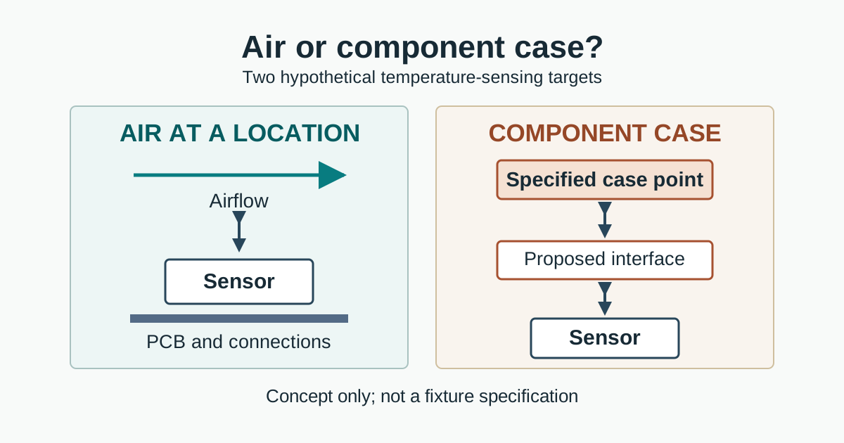
A temperature sensor reports the temperature of its sensing element. That may be close to the air around it, the PCB beneath it, or a nearby component—but proximity alone does not establish which one dominates.
Start the design with a measurable question: What temperature, at what location, during which operating modes, must the reading represent? Then define an allowable error and a response-time criterion before choosing the layout. An air monitor near an enclosure inlet and a monitor of a power-device case can require opposing thermal paths, even if they use the same sensor IC.
Define the temperature before designing the path
Several temperatures can coexist within a small area:
- Air temperature is the temperature of the air at a stated location. Air entering an enclosure may differ from air leaving it or passing a hot component.
- Sensor-element temperature is what the sensor principally responds to, subject to its electrical and calibration errors.
- PCB surface temperature is local to a particular board position and layer stack. It is not automatically representative of the whole board.
- Component surface or case temperature is the temperature at a specified point on the outside of the component.
- Semiconductor junction temperature is internal to the device. A case or board sensor does not automatically reveal the junction temperature or the hottest internal spot.
For each requirement, specify the reference location, operating range, acceptable steady-state difference and response definition. Also state whether the requirement applies at startup, idle, maximum load, fan failure, or other modes. If a product actually needs junction temperature, consider a suitable junction-sensing arrangement, such as a supported remote diode, as a different architecture with its own electrical and thermal validation—not as an automatic equivalent of a surface measurement.
Two hypothetical architectures
The following designs are examples for comparison, not prescribed geometries or performance claims.
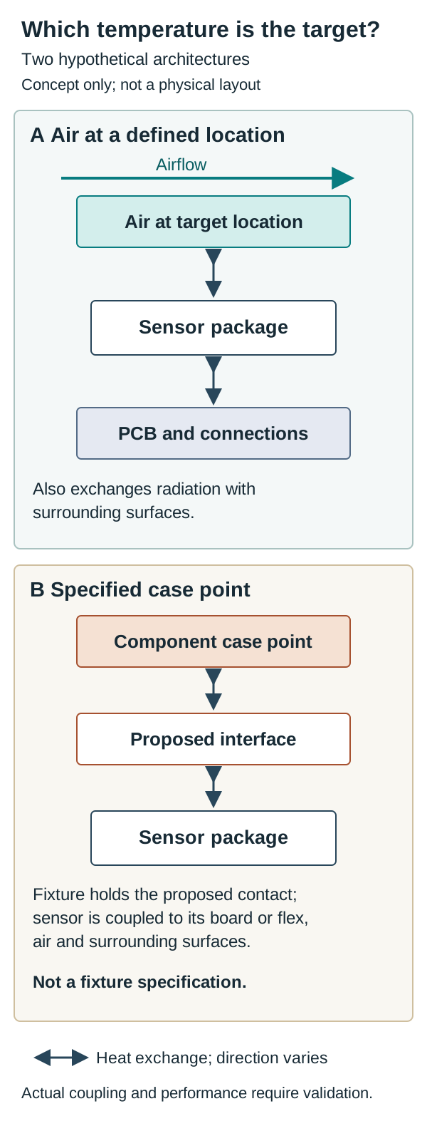
Architecture A: air at an enclosure location
A board-mounted sensor sits on a narrow PCB tongue or small daughterboard near a defined air-sampling location. Its electrical connections remain sufficient for the device, while unnecessary copper connections to warmer board regions are reduced. An enclosure opening or airflow route is designed to bring representative air past the sensor.
The intended path is air → sensor package → sensing element. Unwanted paths include heat conducted from the main PCB, radiation from warm surfaces, and air already heated by electronics upstream.
This approach may improve air tracking, but the isolation can make the sensor mechanically vulnerable or leave it in a stagnant pocket. An opening can also expose the assembly to contamination or allow an external draft to dominate the intended internal airflow.
Architecture B: a specified component surface
A possible architecture uses a sensor on a separate small board or flexible tail, held against a defined component-case point by a purpose-designed fixture. A suitable interface and mounting arrangement must be established for the actual sensor package and component. Check the tolerance chain, permitted contact surfaces, force, electrical isolation and clearances, material compatibility, possible case or solder-joint damage, and any effect on the component's own cooling. Validate the assembled contact through relevant vibration and thermal cycling. The package heat path and complete assembly require validation; this direct-contact concept is not established by every manufacturer's board-mounted examples.
The intended path is component surface → interface → sensor package → sensing element. The sensor is still influenced by its PCB, nearby copper, surrounding air and radiation. Contact pressure, interface thickness and assembly tolerances can change the result.
This architecture is not automatically a junction monitor. It also may track the component poorly if its board connections conduct more heat from a different source than the interface conducts from the target.
| Design choice | Intended benefit | New risk or competing path | What to verify |
|---|---|---|---|
| Reduced copper coupling in A | Reduce heat conducted from the main board | Longer settling, electrical or mechanical compromises | Air error across board-load and airflow modes |
| Designed enclosure exchange in A | Bring air from the specified region to the sensor | Draft sensitivity or contamination | Reference air at the specified point in each enclosure state |
| Contact interface in B | Couple the sensor to the chosen case point | Variable pressure, insulation or assembly problems | Error against a surface reference, including repeat assemblies |
| Copper or vias near B | Help establish a desired board-side path in a suitable design | Couple the sensor to an unrelated heat source or heat sink | Compare target, sensor-region PCB and neighboring temperatures |
| Local isolation in B | Reduce competing board heat | Weaken the assembly or interrupt electrical paths | Mechanical, electrical and thermal tests together |
TI's SNOA967A Rev. A PCB guidelines for surface-mount temperature sensors discuss PCB heat paths and examples of ambient and nearby-component sensing. The guide does not validate Architecture B's proposed direct-case-contact fixture. Its examples are useful starting points, not universal dimensions, via counts or accuracy promises.
Follow every significant heat path
Conduction: often the hidden path
Heat conducts through sensor leads or pads, solder, copper, vias, the laminate, mounting hardware and any material touching the package. In an air-sensing design, a large copper connection to a warm regulator can pull the sensor reading away from local air temperature. In a surface-monitoring design, a deliberate conductive path may be useful—but only if it connects to the specified target rather than to a different thermal source.
Thermal vias can move heat between board layers, but their effect on a sensor depends on what those layers are coupled to. Evaluate them as part of the complete sensing path, not simply as a way to cool the board.
Package construction matters. The exposed package surface, terminals and underside need not couple equally to the sensing element. Check the sensor’s documentation before assuming that placing its top, bottom or leads against a target creates the strongest path. Coating, adhesive and thermal-interface material can also add resistance or thermal mass.
A board test point can help diagnose conduction, but it measures only its own location. A temperature measured beside the sensor is not proof of the temperature inside the sensor package.
Convection: define which air counts
Air carries heat into and out of both architectures. In Architecture A, that is the desired coupling only when the air passing the sensor represents the specified location. A fan, cable bundle, vent or enclosure wall can redirect the flow. Heated exhaust recirculating toward an inlet sensor can change its reading without any change in the room.
In Architecture B, moving air can cool the sensor package or interface relative to the component surface. A fan-on result therefore does not establish fan-off performance, or vice versa.
The Sensirion Humidity and Temperature Design Guide, Version 2, March 2024 discusses board conduction and air effects in assembled air humidity and temperature systems. It is not guidance for a case sensor or junction thermometer, but the distinction between sensor-level characteristics and assembled-system behavior remains important here.
Radiation: a path without contact
A sensor exchanges radiant heat with surrounding surfaces. A nearby hot shield, dark enclosure wall or power component can influence the package even when conduction is reduced. Surface temperature, area, emissivity and line of sight all matter.
A shield can reduce a radiative influence, but it can also obstruct airflow or become another conductive or radiative surface. Compare shielded and unshielded configurations when radiation is plausible; do not assume a shield is neutral.
Thermal mass and mounting
A large copper area, thick interface, bracket or enclosure wall can slow a temperature change at the sensor. Low thermal mass can improve responsiveness, but may make a reading more sensitive to short drafts or noise. Conversely, a massive mounting feature may stabilize a reading while masking a fast component temperature rise.
Mounting is part of the thermal circuit. Screws, clips and adhesive can conduct heat, alter contact pressure or change with vibration and temperature cycling. Test the intended production mounting, not just a convenient laboratory attachment. For repeated temperature exposure, define the specimen, profile and failure criteria as part of the thermal cycling test plan.
Separate self-heating from nearby heat
Sensor self-heating is heat produced by the sensor or its own excitation and circuitry. It can depend on supply conditions, measurement rate or duty cycle. For a resistive element, excitation can heat the element itself; for an IC, operating mode and current can matter. Follow the particular device specifications.
Nearby heat comes from other sources: regulators, processors, pull-up networks, power devices or their heated copper. Nearby heat may reach the sensor through the PCB, air or radiation.
To distinguish them, hold the surrounding operating condition as stable as practical and vary the sensor’s permissible excitation, sampling rate or duty cycle. Allow sufficient settling and compare against a reference. Then restore the intended sensor mode and vary nearby load or airflow. A change in reading is evidence to investigate, not by itself proof of a single heat path.
Changing an electrical test input or substituting a resistance can exercise an electrical measurement chain, but it does not verify sensor-to-target thermal contact. Likewise, a calibration offset found at one condition does not necessarily correct a gradient that changes with load or airflow.
Slots and copper changes are system changes
A slot, narrow board neck or copper reduction can increase thermal resistance between regions. It can also create problems unrelated to temperature measurement.
Before cutting or reshaping the board, check:
- Electrical return paths: A split or narrowed reference plane can force return current around an opening, increase loop area or affect signal integrity and emissions. Preserve the paths required by the circuit; include a return-path review rather than assuming less copper is harmless.
- Mechanical strength: A tongue or slotted region may flex during handling, connector insertion or vibration. Check board support and the strain imposed on solder joints and any flexible connection.
- Assembly and contamination: Openings and narrow features can affect depanelization, handling, cleaning and coating. Slots may collect debris or fluids, depending on orientation and environment.
- Reliability: Contact pressure, interface materials, solder joints and copper features can change with thermal cycling, moisture or repeated mechanical stress.
- Electrical and safety clearances: Any contact material, mounting feature or copper change must satisfy the applicable isolation and clearance requirements.
Do not select a slot size or copper pattern from a generic rule. Evaluate the complete electrical, mechanical and thermal design against the sensor and assembly specifications.
Build a falsifiable validation matrix
Write the acceptance rule before testing. For example, define the permitted steady-state difference from the reference, the response metric, the required operating modes and how uncertainty affects the decision. A result that cannot distinguish a pass from a fail should be recorded as inconclusive, not silently accepted.
Use reference measurement chains with valid calibration and traceability evidence applicable to the measurand and range, and record their calibration status. For the case reference, document its position and repeatable attachment material, pressure or bond geometry as applicable; evaluate probe conduction, changes to target cooling and differences from any inaccessible target point. Place the air reference to avoid significant flow blockage and radiation pickup where feasible. Record remaining spatial bias and disturbance and resolve their effect on interpretation. Calibration alone does not validate placement, contact, loading or dynamic response. Include resolution, repeatability, timing and relevant environmental effects in the uncertainty assessment.
| Test question | Setup and reference | Record and decision evidence |
|---|---|---|
| Is the intended location measured? | Identify A's enclosure air point and B's component-case point, along with each reference position. Evaluate spatial differences and inaccessible target points. | Record exact positions, mounting and reference uncertainty. If the sensor occupies that point, assess the difference between an adjacent reference point and the intended point. |
| Can the probe disturb the result? | Compare a practical reference attachment or placement with an alternative where feasible. Evaluate case-probe conduction and attachment effects on cooling, and air-reference flow blockage and radiation pickup. | Record remaining bias and disturbance and resolve their effect on the comparison. |
| What happens at idle and hot load? | Run the defined idle and high-load modes long enough to meet a predeclared settling criterion. Measure the target and selected nearby PCB or heat-source locations. | Compare the sensor and reference over the same steady interval. Record signed error, variation and nearby gradients. |
| Does it respond adequately? | Start from a defined condition; log startup and a specified load transition with synchronized timestamps. Include both rising and falling transitions if relevant. | Record response time using the predeclared threshold, filtering and time origin. Also record overshoot, lag and any failure to reach the threshold. |
| Does the enclosure or airflow change the result? | Test the intended enclosure, vent and fan states, including relevant assembly variations and fault modes. Place the reference at the specified location for each case. | Compare steady error and transient response separately. A result with the enclosure open does not establish closed-enclosure performance. |
| Is self-heating significant? | At a stable surrounding condition, vary permissible sensor excitation or operating duty while monitoring the reference. | Record the reading shift and settling behavior; repeat at the intended production setting. |
| Does the result repeat? | Test multiple representative boards and assemblies, including relevant contact, mounting and geometry variation. Repeat selected transitions. | Report each board and condition, not just the best trace or an overall average. Investigate outliers and revise the design or test. |
Define the measurand, including the PCB location and relevant thermal and timing conditions, and define signed error as the sensor indication minus the reference estimate of that temperature. Set out the uncertainty budget and its coverage factor or probability, and quantify or bound the bias caused by the reference position, for example using the temperature gradient and separation under applicable conditions. State whether that bias is corrected, with residual correction uncertainty included, or left uncorrected and explicitly accounted for in the interval and decision; do not omit or double-count it. Specify the decision rule, including the disposition of intervals that overlap a limit. For example, accepting only when the absolute observed error plus expanded uncertainty is within a project-selected limit, and treating overlapping intervals as indeterminate, is a policy to be agreed for the actual measurand, uncertainty model and risk decision, not a universal rule. Each relevant board and operating condition must be assessed separately rather than hiding failures in a pooled uncertainty. Define response time and its uncertainty model equally explicitly, including probe lag and timestamp alignment, and specify how response-time intervals within, outside or overlapping the applicable limit will be dispositioned.
A hypothetical calculation
Suppose a component-surface reference starts at 20 °C and settles at 50 °C after a load change. A board-mounted sensor starts at 20 °C and settles at 48 °C. These values are invented to illustrate the calculation, not measured results or an acceptance limit.
The steady-state signed error is:
48 °C − 50 °C = −2 °C
For this example, define a common threshold as 90% of the reference’s total rise. The rise is 30 °C, so the threshold is 20 °C + 0.9 × 30 °C = 47 °C. If the reference crosses 47 °C at 20 seconds and the sensor crosses it at 70 seconds, the sensor reaches that threshold at 70 seconds, or 50 seconds after the reference crossing. This is a difference between crossings of the chosen absolute threshold, not the sensor's own 90% response time: the sensor's final rise is only 28 °C.
The crossings above are assumed to be the first valid rising crossings. Define filtering, persistence and how to report multiple crossings or a threshold that is never reached before testing. The calculation does not establish a pass. A real decision also needs the specified limits, timing and temperature uncertainties, settling definition, and results across the required modes and assemblies.
Analog Devices AN-892 defines one time constant as the point at 63.2% of a final step for its first-order model; a real assembly is not necessarily first order. A sensor's 90% response is relative to its own initial-to-final change. This example instead compares crossings of a common absolute threshold, which is not necessarily either metric. Define a common time origin and report timing uncertainty. Report separately when a reading is already at or above the threshold at the origin or never crosses it within the observation period; do not infer a missing crossing or timing difference.
For a PCB or assembly inquiry, use the quote page and share the design files, sensor part number, intended measurement location and relevant mechanical or thermal requirements. Confirm fixture, calibration and environmental testing scope for the project.
FAQ
Can one board-mounted sensor represent both enclosure air and a hot component?
Possibly in a particular operating condition, but the objectives compete. Air sensing benefits from coupling to representative air; surface sensing benefits from coupling to the target. Validate each claimed measurand independently across the required modes.
Is the closest sensor always the best component monitor?
No. A nearby sensor can be dominated by PCB copper, airflow or another heat source. Define the surface point and verify the complete thermal path against a suitable reference.
Does a large copper pour always improve temperature tracking?
No. It can improve coupling to one thermal region while adding thermal mass or conducting heat from somewhere else. Its value depends on the target and must be tested.
Can a surface measurement be converted directly to junction temperature?
Not generally from a single surface reading alone. The difference depends on the device, heat flow and operating conditions. Use an appropriate model or junction-sensing method and validate it for the application.
When should validation be repeated?
Repeat the relevant tests after changes to sensor package, copper, mounting, interface material, enclosure, airflow, nearby power dissipation or sensor operating mode. Even a change intended to improve assembly can alter the thermal path.