
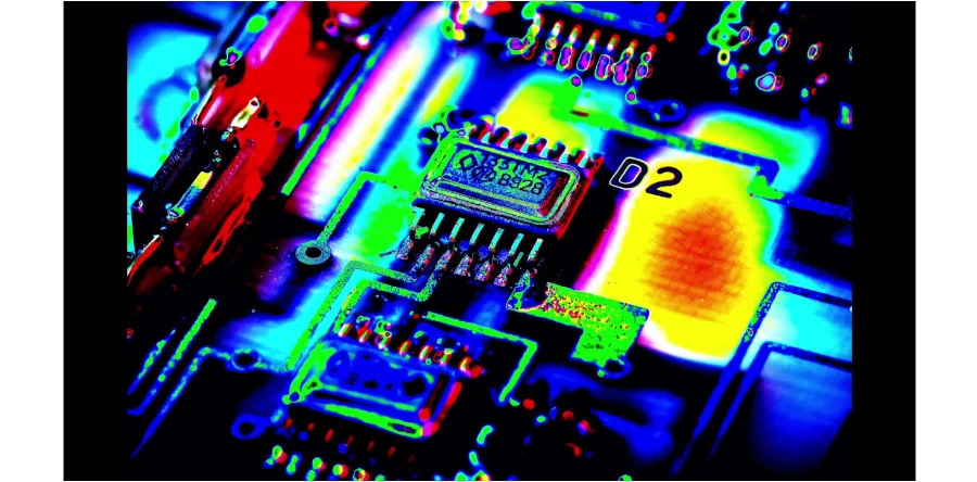
Thermal cycling exposes a defined PCB or assembled test vehicle to repeated temperature changes to investigate selected failure mechanisms. The useful result is a traceable relationship between construction, specimen temperature, exposure and observed failure—not a general guarantee of field lifetime. For a HilPCB request, agree the test provider, samples, profile, monitoring and report scope before release.
Advanced Thermal Cycling Testing Methodologies and Stress Analysis
Choose the profile from the test article, governing method and intended mechanism. Chamber air temperature, transfer time and actual joint/board temperature are different quantities. Instrument representative locations and confirm stabilization at the required extremes before counting dwell time.
Core methods and controls:
- Air temperature cycling: Controlled heating/cooling with specified ramps and dwells; record measured specimen temperatures and loading. No single temperature range or ramp rate fits all boards.
- Thermal shock: Rapid transfer between environments imposes different gradients and can activate different mechanisms. Liquid immersion needs compatible specimens, media and a qualified method; neither the specimen temperature nor its internal joints change instantaneously.
- Gradient or multi-zone exposure: Use only when spatial gradients are part of the objective. Record location and fixture effects; this is not automatically equivalent to uniform chamber cycling.
- Fatigue modeling: Coffin–Manson-type models apply to particular fatigue mechanisms and constructions. Fit and validate the model before extrapolating to a field load spectrum; one acceleration factor cannot cover all failure modes.
- Electrical monitoring: Define monitored nets, resistance/event limits, measurement cadence and intermittent-failure detection. End-point continuity alone can miss a transient open.
- Failure analysis: Localize cracks, delamination or other damage and distinguish manufacturing defects from the intended wear-out mechanism.
Differences in thermal expansion can strain solder joints, plated vias and material interfaces. The result depends on geometry, materials, constraints and the full thermal history. A high-Tg PCB label alone does not determine fatigue life or the appropriate test profile.
Manufacturing Integration and Assembly Reliability
Effective thermal cycling implementation requires seamless integration with manufacturing processes, enabling comprehensive verification while maintaining efficiency across diverse applications.
Production Integration: Reliability planning begins during design because material selection, stackup and component layout influence stress distribution. For metal-core PCB assemblies, account for the actual mass, constraints, insulation and heat path in the specimen profile. Confirm loading, fixtures and data acquisition with the test provider; they affect specimen response and monitoring access.
Assembly Considerations: SMT assembly operations integrate protocols addressing solder paste selection and reflow optimization under thermal stress. Testing programs evaluate process quality through statistical analysis of fatigue patterns. For turnkey assembly, specify whether cycling is qualification, process evaluation or production screening and whether it is included in the order.
Volume and sampling: For large-volume assembly, define the lot/sample selection, test capacity and loading plan. Use samples representative of the released process, include relevant variation and record any excluded or censored specimens. A destructive qualification test is not automatically required on every production unit.
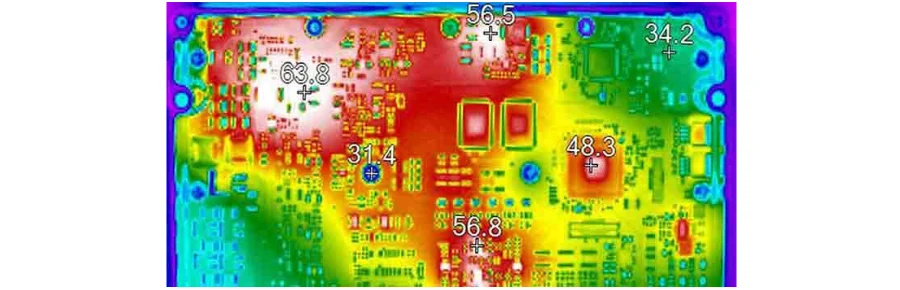
Temperature Stress Testing and Component Analysis
Comprehensive programs address diverse thermal mechanisms across components, providing detailed characterization supporting design optimization and quality decisions throughout development and manufacturing phases.
Solder Joint Evaluation: Evaluate solder fatigue and interfacial damage from expansion mismatch, alongside aging effects such as intermetallic growth during time at temperature. Testing tracks joint temperature, resistance, and mechanical integrity enabling early fatigue detection. If a high-speed PCB requirement includes signal integrity across temperature, define the corresponding electrical measurements in addition to continuity.
Substrate Assessment: Testing evaluates expansion characteristics, delamination resistance, and dimensional stability. Monitor the specified dimensions/electrical parameters before, during where required, and after exposure. Accelerated observations support a prediction only when the failure mechanism and extrapolation model are justified.
Interface Validation: System-level testing evaluates via integrity, attachment reliability, and thermal interface performance under cyclic stress. Advanced diagnostics provide failure localization enabling rapid process improvement.
Standards and Quality Management
Professional operations adhere to comprehensive standards ensuring consistent verification while maintaining traceability supporting regulatory compliance.
Standards Compliance: Applicable references may include IPC-SM-785 (solder-attachment reliability guidance), IPC-9701 (solder-joint performance testing), JESD22-A104 (component temperature cycling) and selected MIL-STD-810 environmental methods. Define the test article, revision, temperature profile, dwell time, sample size and failure criteria in the approved plan.
Statistical analysis: Report sample size, cycles/exposure to each failure, survivors, censoring and confirmed mechanisms. A Weibull or other model needs suitable data and assumptions; show uncertainty and any acceleration validation. A no-failure test does not by itself establish a precise mean life or process capability index.
Data management: Retain sample/lot/revision IDs, construction, instrumentation/calibration, chamber and specimen temperature logs, interruptions, electrical events and failure-analysis results. Agree raw data, report format and retention; a generic service description does not establish an integrated database or predictive model.
Manufacturing and Test Handoff with HilPCB
HILPCB offers thermal-cycling testing with chamber, profile control, specimen monitoring and failure-analysis support. The available air-cycle equipment envelope is −65°C to +150°C at 5–15°C/min, subject to the specimen, transition method and build profile. Our ISO 9001 manufacturing system supports design, material, process and test planning across prototype-to-volume fabrication and assembly. Payment, shipping and customer-support arrangements are confirmed with the order; the selected cycle is not a lifetime guarantee.
Release the actual board/assembly construction, material and process revisions, fixtures, power state and test objectives. Identify which inspections and electrical tests precede/follow exposure, who performs cycling and failure analysis, and who approves deviations or design changes. Any quality-system certificate should match the current site and scope.
Confirm the available chamber/profile, monitoring, sample quantity and schedule in the quote. Keep the manufacturing acceptance decision separate from the product owner's field-reliability model and system qualification.
FAQ
What temperature ranges are used in thermal cycling testing?
Use the applicable method and approved plan for the actual component, bare board or assembly. Define specimen minimum/maximum, ramps, dwells and tolerances; commercial, automotive or military labels alone do not select one profile. Avoid exceeding material/component limits in a way that creates irrelevant mechanisms unless that overstress is the stated objective.
How many thermal cycles are required for a useful assessment?
Define the objective first: qualification against a specified cycle count, a comparison of constructions or a test-to-failure study. Select sample size, duration and stopping rules with the required confidence and expected mechanism. There is no universal 100–1000 or 10000-cycle rule for all PCB products.
What failure mechanisms can thermal cycling reveal?
Depending on construction and monitoring, cycling can reveal solder fatigue, via or lead cracking, delamination and interface degradation. Confirm the mechanism through failure analysis. Programs may also include PCB vibration testing; combined stresses need their own defined sequence or simultaneous profile rather than assuming all separate tests are interchangeable.
How do accelerated conditions relate to actual operation?
Relate measured specimen history to the field temperature/load spectrum and confirm that the same mechanism dominates. A fatigue model needs construction-specific parameters and validation; test temperature amplitude or cycling frequency alone does not establish service life.
What parameters should be controlled during testing?
Control the approved temperature limits, ramp/dwell, loaded-chamber uniformity, sensor placement, fixture constraints, power state and monitoring thresholds. Address condensation where relevant. Use tolerances from the selected method and equipment verification, rather than a universal ±2°C claim.
Can cycling predict reliability in different climates?
It can provide evidence about selected thermal mechanisms. Humidity, condensation, corrosion, electrical bias and mechanical loads may need separate or combined assessments. A temperature-only pass is not an all-climate reliability prediction.