
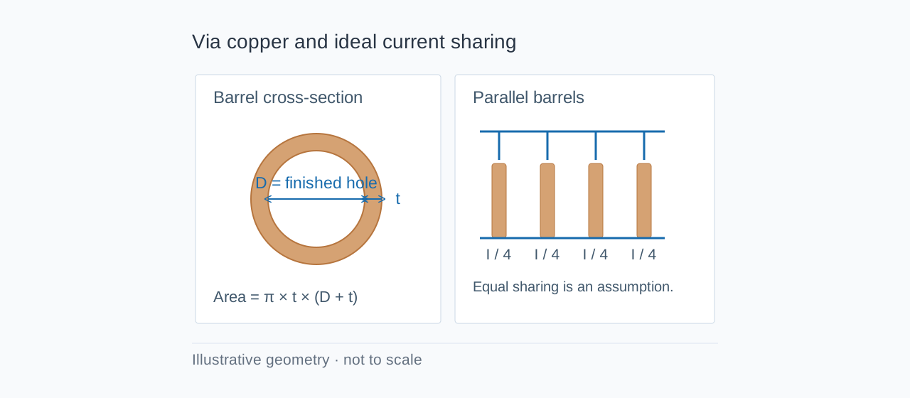
A power trace can be wide enough and still feed a weak layer transition. The via barrel has its own copper cross-section, resistance and heat path. Start with finished hole diameter and minimum hole-wall copper, then check the connections into the barrel and the actual sharing between parallel vias.
The PCB via current calculator compares barrel resistance, voltage drop, copper loss and heuristic current estimates. Its most useful result is a transparent comparison between geometries. A single calculated current does not establish a qualified via rating.
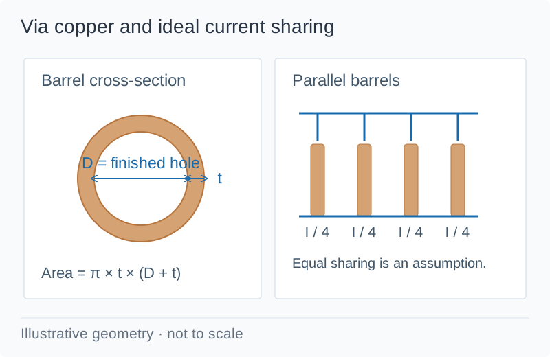
Which diameter and copper thickness should you enter?
Use the finished internal hole diameter, not the drill-tool diameter, for this calculator. Radial plating is the copper thickness on one hole wall. It is separate from outer-layer copper weight: a board with 2 oz external copper does not automatically have a particular barrel plating thickness.
For finished internal diameter D and radial copper thickness t, the barrel's conducting cross-section is:
A = π × [(D/2 + t)² − (D/2)²] = π × t × (D + t)
Use millimetres for both dimensions to obtain square millimetres. The common thin-wall approximation πDt drops the t² term. With D = 0.30 mm and t = 0.025 mm, the exact annular area is 0.0255254 mm². The thin-wall result is about 7.7% lower than the exact area.
The barrel length is the length of the current-carrying segment being assessed. For the through-board example below it is 1.60 mm. A connection between nearby inner layers can have a shorter DC conduction segment, while the remaining barrel can still matter as a high-frequency stub. A resistance comparison does not analyze that stub.
Worked example: a 3 A transition with one, two or four vias
Enter these values in the calculator:
| Input | Value |
|---|---|
| Finished hole diameter | 0.30 mm |
| Radial copper plating | 25 µm |
| Barrel length | 1.60 mm |
| Local ambient | 25°C |
| Assumed temperature rise | 10°C |
| Total load | 3 A |
| Via count | Compare 1, 2 and 4 |
The resistance calculation assumes 35°C copper. It uses ρ20 = 1.724 × 10⁻⁸ Ω·m and a temperature coefficient of 0.00393/°C:
R = ρ20 × [1 + 0.00393 × (T − 20)] × length / area
Convert length to metres and area to square metres. For N identical barrels with ideal equal sharing, Rarray = R/N, voltage drop = I × Rarray and total barrel loss = I² × Rarray.
| Via count | Current per via | Array resistance | Drop at 3 A | Total barrel loss |
|---|---|---|---|---|
| 1 | 3.00 A | 1.14435 mΩ | 3.43305 mV | 10.2992 mW |
| 2 | 1.50 A | 0.572176 mΩ | 1.71653 mV | 5.14958 mW |
| 4 | 0.75 A | 0.286088 mΩ | 0.858264 mV | 2.57479 mW |
These figures cover copper barrel resistance only. They exclude pad spreading resistance, thermal relief spokes, connecting traces, solder joints and connectors. They also hold copper temperature fixed: the calculation does not solve the new equilibrium temperature after adding vias.
Why is the displayed current estimate not an IPC via rating?
The tool also applies the familiar trace-style expression I = k × ΔT^0.44 × A^0.725 to the barrel cross-section in square mils. For this geometry at a 10°C rise, k = 0.048 produces about 1.90234 A and k = 0.024 produces about 0.951170 A.
Those are heuristic comparisons. The coefficients originate in legacy conductor-sizing practice; assigning them to through and blind/buried via categories does not establish a validated via thermal model. In particular, the two values do not prove that a through via carries twice the current of a blind via.
The arithmetic sum of several heuristic values is still a heuristic. It does not account for shared heating, uneven plating or unequal current entry. Use it to flag a design for further investigation, then confirm the assembly under its intended loading and cooling conditions. The trace-width guide explains the distinction between legacy curve fits and board-specific thermal assessment.
When do parallel vias help less than the ideal calculation suggests?
| Layout condition | Why equal sharing can fail | What to inspect |
|---|---|---|
| Vias in a long row fed from one end | The first barrel can have a shorter access path | Trace/pour resistance into each via |
| Narrow pad entry or thermal relief | Access copper can dominate the transition | Spoke width, count and copper connection |
| Dense hot via cluster | Barrels share the surrounding thermal environment | Temperature with simultaneous loads |
| Different hole sizes or plating | Resistances are unequal | Minimum finished construction and process variation |
| Fast switching edges | Inductance affects transient current distribution | Return path and complete switching loop |
Place vias where the copper can feed them effectively. Increasing the count beyond a narrow neck-down does not remove the neck-down. Compare the via array with the trace width and current calculator and assess fast transitions with the via inductance calculator.
What should you verify before ordering?
Record minimum finished hole size, minimum hole-wall copper, current-carrying barrel length, via count, connection geometry, local ambient and load case. Agree the relevant fabrication inspection with the supplier. For the prototype, measure transition voltage drop at defined points and check stabilized temperature in the populated enclosure.
The Copper Development Association's copper reference publications provide material-property background. TI TIDUCS7, Equation 7 documents the legacy trace coefficient set; it is not a via-rating standard. IPC-2152's scope addresses conductor sizing and thermal context.
FAQ
How much current can a 0.3 mm via carry?
Finished hole diameter alone is insufficient. You also need hole-wall copper, barrel length, connection geometry, thermal conditions and the allowed rise. The worked example gives 1.14435 mΩ at an assumed 35°C; its heuristic current values are comparison outputs, not qualified current limits.
Do four vias carry exactly four times the current?
Only an ideal sum of identical independent estimates scales that way. Equal DC sharing gives one quarter of the barrel resistance, but actual current capacity also depends on access copper and shared heating.
Is 1 oz copper the same as 25 µm via plating?
No. Copper weight normally describes a planar foil or finished layer construction. Specify minimum hole-wall copper separately.
Does filling a via remove its copper resistance?
No. Nonconductive fill does not add an equivalent parallel copper path. A different metallized construction needs a model and process specification that represent its actual geometry.
Compare your via geometry in the calculator, then request a PCB quote with the finished-hole and plating requirements attached.