
Air-gap construction separates flexible sub-stacks in a rigid-flex board over a defined bend region so they can move relative to one another. It can make a multilayer connection easier to fold than a fully bonded stack, but the available bend envelope, individual layer lengths, electrical references and manufacturing process still determine whether the finished assembly works.
Start with the installed shape and movement, then design the layer arrangement with the fabricator. A loose-leaf region is not automatically a qualified dynamic hinge, and the term air gap alone does not specify where layers are bonded or how much space remains after bending. For general construction, see rigid-flex circuit board design; repeatedly moving applications require a dedicated dynamic-flex design and qualification plan.
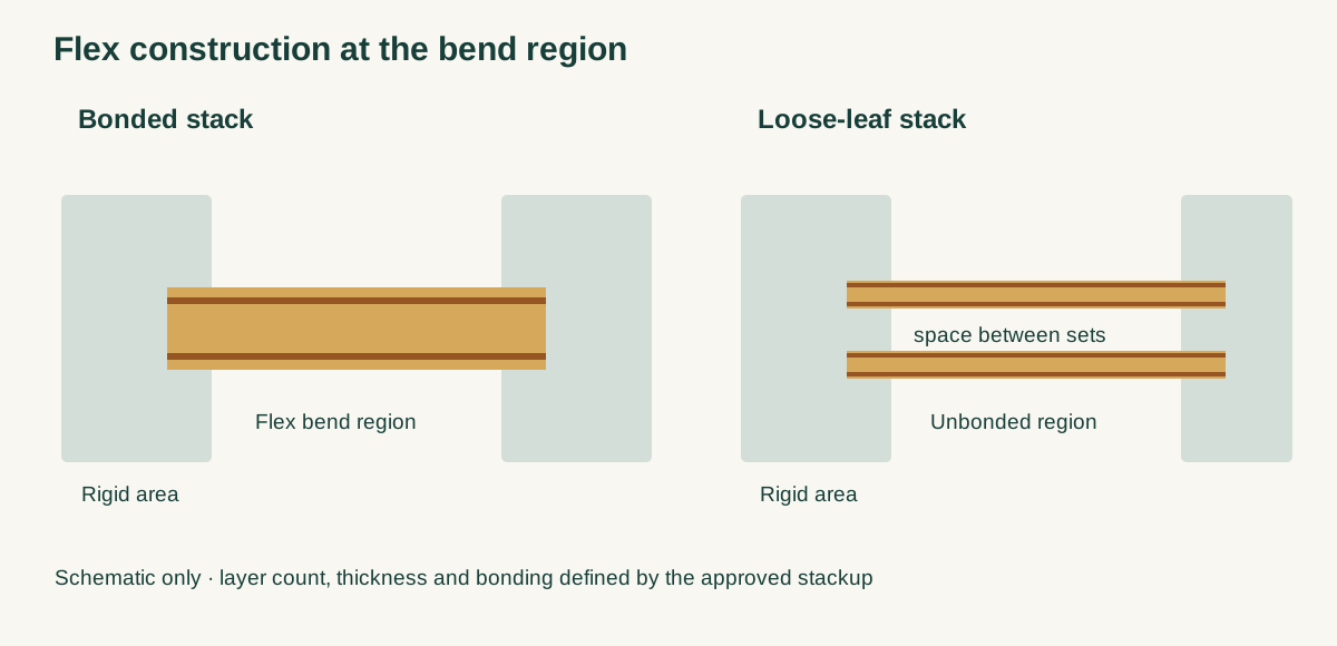
1. What Is an Air Gap in a Rigid-Flex Stackup?
A rigid-flex construction joins flexible circuits to rigid areas within a single interconnect. In a fully bonded bend region, the flex layers and their bonding materials act more like one combined laminate. In an unbonded or loose-leaf region, two or more flex sub-stacks are separated over a specified length and may slide or move relative to each other during bending. They remain integrated into the rigid sections according to the approved construction.
The space shown between the sub-stacks in a flat drawing is a schematic representation. Its actual shape changes as the part is handled and installed: layers can approach or contact each other. An air gap is not necessarily a controlled, permanently uniform dielectric thickness. Specify the bond/no-bond boundaries, materials, interfaces and finished geometry on the stackup and drawing instead of leaving them to the name of the construction.
A sub-stack may contain one or more copper layers with its own dielectric and coverlay. The appropriate number depends on routing, shielding, bend behavior and process capability. Do not assume a universal two- or three-layer limit without checking the applicable design requirements and fabricator's proposed construction.
2. When Should You Consider Loose-Leaf or Bookbinder Construction?
| Design condition | Starting option to evaluate | Question that controls the decision |
|---|---|---|
| Few conductors and a generous, fixed installation bend | Bonded flex section | Can a simpler stack meet bend, routing and assembly requirements? |
| Multiple flex layers with a fixed bend | Separated sub-stacks | Can each set bend within the envelope without buckling or excessive contact? |
| Multiple sets must follow a tight, known installed curve | Bookbinder construction with different set lengths | Can the drawing and tooling control each path length and the final shape? |
| Repeated movement in service | Dedicated dynamic-flex design and test | Can the actual motion, cycle count, environment and failure criteria be qualified? |
| Controlled impedance crosses the bend | Joint mechanical and electrical stackup review | Where are the reference conductors, and how stable is the dielectric geometry through movement? |
Bookbinder construction is a particular way of managing separated layers: the outer sub-stacks are made progressively longer to follow the longer path around a bend. It is distinct from merely leaving layers unbonded. Different lengths add tooling and registration constraints, so assess whether a larger bend radius, more available flex length or fewer layers solves the problem first.
For a repeated-motion design, record the complete motion rather than only a nominal radius: minimum local radius, bend angle, direction, stroke, speed, cycle count, temperature, mounting support and electrical failure criteria. A design that folds once for installation cannot be presumed suitable for a moving hinge.
3. Why Can Separated Layers Help a Bend?
When a flat laminate bends, material away from its neutral axis changes length: one side is in tension and the other in compression. A thicker bonded section generally places its outer surfaces farther from that axis. Separating a stack into thinner sub-stacks can allow each to bend around its own neutral region rather than forcing the whole assembly to behave as one laminate.
For an ideal homogeneous beam under a uniform bend, the approximate surface strain is ε ≈ t/(2R) when R is the neutral-axis radius and thickness t is small relative to R. This is a screening model, not a flex-life formula: actual copper strain depends on layer stiffness, copper position, material properties, nonlinear behavior, contact and the bend shape.
As an illustration, at a 5 mm neutral-axis radius a symmetric 0.40 mm homogeneous beam gives an estimated outer-surface strain of 0.40/(2 × 5) = 4%. A separate 0.10 mm symmetric beam at the same radius gives approximately 1%. The comparison illustrates the geometric effect of thickness; it does not prove that a real separated design has one-quarter of the copper strain or meets an allowable strain. The sets may bend at different radii, touch or buckle, and neither number establishes an acceptable design.
In a short flex span or a tight U-bend, the inner set can bunch up while outer sets constrain it. A nominally unbonded stack can therefore develop a local kink much tighter than the intended radius. Review the entire movement and installation sequence in three dimensions, including tolerances and clearance to the enclosure, not just the flat board outline.
4. How Do You Estimate Bookbinder Length Differences?
For an ideal concentric circular bend, the length along a path is L = θ R, where θ is the bend angle in radians and R is the radius of that path. If two sub-stack centerlines follow the same angle and their radii differ by H, their curved lengths differ by:
For a hypothetical 90° bend, θ = π/2. If the two centerline paths are separated radially by 0.20 mm, the outer path is approximately (π/2) × 0.20 = 0.314 mm longer over the curved portion. Any straight portions must be added separately. The 0.20 mm is an assumed centerline-to-centerline spacing in the installed bend, not a specified flat air-gap width.
This estimate identifies why equal flat lengths may be inadequate. It is not production artwork: the actual path depends on layer thickness, bending shape, transition position, tolerances, contact and forming method. The fabricator must determine achievable individual lengths and registration with the designer, and the mechanical team must check the actual installed envelope. The IPC-hosted technical paper “Unique Implementation of a 15 Layer, Unboned/Looseleaf, Bookbinder Rigid Flex with Backdrill and LGA Interconnect,” by John Dangler, Jeffrey Taylor and Cynnthia A. Verbrugge, describes sub-stack lengths and tooling tailored to one installation. It is a case study, not an IPC standard or a universal design recipe.
5. What Must the Stackup and Drawing Define?
The fabrication package should show the stack in both the rigid and flexible regions. Identify each copper layer and flex sub-stack, base film and coverlay, rigid materials, bonding layers and where the bond is deliberately absent. Call out the boundary of each unbonded region relative to manufacturing datums. A label such as “air gap between layers” leaves too much unresolved.
| Drawing item | Information to provide | Why it matters |
|---|---|---|
| Rigid and flex stackups | Layer order, materials, thickness targets and tolerances | Establishes the actual construction and the thickness of each bending set |
| Bond/no-bond boundaries | Locations and datums for each interface | Defines where motion is possible and where load transfers to the rigid section |
| Formed geometry | Inside bend radius, angle, bend direction and installed clearances | Lets design and fabrication evaluate the real mechanical envelope |
| Sub-stack lengths | Individual lengths or a fabricator-approved length scheme and measurement datums | Prevents an equal-length assumption in a bookbinder bend |
| Transition and coverlay | Coverlay ends, reinforcement or fillet requirements and any restrictions | Avoids concentrating a bend at an uncontrolled material edge |
| Holes and copper | Hole/transition keep-outs, critical conductors and tolerances | Supports drill, plating and bend-region review |
| Test and acceptance | Applicable specification and revision, test conditions, sample and report | Distinguishes board acceptance from product-level life qualification |
The coverlay may extend into the rigid area, with its termination and any bondply cutback defined by the stackup and fabrication process. Hole clearance depends on that construction. Do not adopt a single generic hole-to-transition distance as a guaranteed capability. Ask the fabricator to review the hole location against coverlay, adhesive, registration and lamination details, especially where plated holes pass through changing material regions.
6. How Does Air-Gap Construction Affect Signal Integrity?
Separated mechanical layers are also separate electrical structures. For controlled-impedance traces, identify the signal layer, reference layer, dielectric, copper thickness, geometry and target in each region: rigid, transition and flex. A reference on a different loose sub-stack may change its distance from the signal as the assembly bends or the layers touch. That changes the field environment and can affect impedance or coupling; a nominal flat gap should not be treated as a stable dielectric without analysis and measurement.
Where practical, discuss keeping a controlled signal and its intended reference within a mechanically defined sub-stack. That can increase the thickness of that set, so it is a tradeoff with bend performance rather than an automatic rule. If a return path changes at a transition, review the entire channel and the relevant return-current path. Specify the impedance target and tolerance, trace identifiers, required coupon configuration and the measurement conditions, including whether the flex is flat or formed. A coupon that omits the real transition cannot by itself prove the installed channel.
For broader electrical design, see rigid-flex high-speed signal integrity. For base-film and bonding choices, see rigid-flex substrate materials.
7. How Are Fabrication and Reliability Verified?
Separate three questions: can the board be built to the drawing, does it survive assembly, and does the assembled product survive its intended use? An electrical continuity test can detect opens or shorts at the time of test; it does not establish remaining fatigue life. A microsection can show features at the sampled location, but it is destructive and cannot inspect every joint in every board. Coupon-based thermal testing can assess the specified interconnect construction under a defined profile; it does not automatically qualify the moving flex region.
For a flex-to-install part, agree on the number of handling bends, fixture, minimum radius and inspection before and after assembly. For repeated motion, define a representative fixture, cycle profile, environment, electrical monitoring and failure threshold. If strain relief or a protective material is used, include it in the test configuration and consider its effects on the local bend. Evaluate the finished assembly, not an isolated strip, when supports and enclosure contact influence motion.
Moisture handling and any bake before assembly must follow the material supplier's instructions and the fabricator/assembler's approved process for the actual construction. There is no single bake temperature or time that can be inferred from the presence of an air gap. Similarly, specify the applicable IPC-2223 design and IPC-6013 performance revisions and class in the order where required; confirm the actual clauses and acceptance criteria rather than using an unverified blanket bend multiplier.
8. What Should Be Sent for a Rigid-Flex Quote?
Before layout is frozen, request a quote with the board data and a mechanical drawing or model of both flat and installed states. Include:
- Layer order, material preferences, thickness limits, bond/no-bond regions and any proposed sub-stack lengths.
- Bend locations, inside radii, angles, installation sequence, clearance envelope and whether motion is repeated.
- Copper routing, plated-hole and coverlay details near transitions, plus areas that must remain free of adhesive or reinforcement.
- Controlled-impedance nets and references, allowed tolerance, coupon and measurement requirements.
- Applicable workmanship class, test conditions, sample size, documentation and approval authority for design changes.
- Quantities, panel or carrier constraints, assembly temperatures, handling requirements and expected rework or service access.
The designer owns the installed envelope and product requirements. The fabricator confirms the stackup and process that can produce the board. The assembler reviews support, handling and reflow. The product owner defines qualification and decides whether test evidence is adequate for its application.
HILPCB's rigid-flex PCB offering lists rigid-flex stackup review, bookbinder construction and dynamic bend or thermal testing options. The feasible construction and test scope must be confirmed against the submitted design and quotation.
FAQ
What is an air gap in a rigid-flex PCB?
It is an intentionally unbonded region between flex sub-stacks that allows relative movement during bending. The gap's dimensions and the bond boundaries must be defined for the construction; it should not be assumed to stay uniform in the installed shape.
Is bookbinder construction the same as loose-leaf construction?
Bookbinder designs use separated sub-stacks with different lengths so outer paths can follow a bend. Loose-leaf describes the unbonded arrangement and does not by itself specify different lengths.
Can an air gap guarantee a smaller bend radius?
No. Separation can reduce constraints associated with a thick bonded stack, but the permitted radius depends on materials, individual set thickness, copper, local geometry, installation and required life. Verify the actual design with the fabricator and a suitable test.
Is air-gap rigid-flex suitable for repeated bending?
It may be considered as part of a dynamic-flex design, but separation alone does not establish fatigue life. Define and qualify the complete motion, support, environment, cycle count and electrical failure criteria.
Does an air gap solve plated-hole reliability problems?
No. Via reliability depends on the actual rigid-region material stack, hole construction, processing and thermal exposure. Define the construction and use appropriate inspection and qualification for the specified product.