
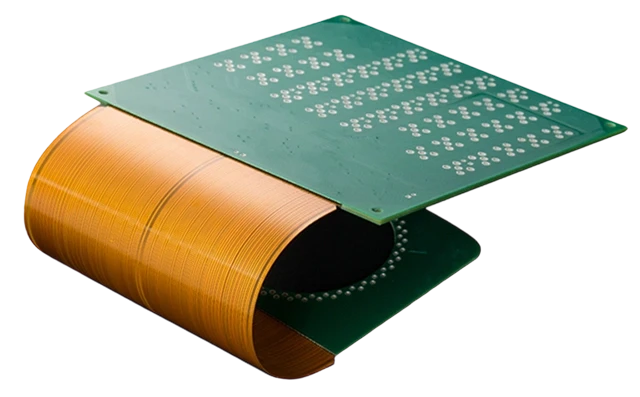
Connecting multiple printed circuit boards across an industrial chassis or handheld enclosure presents an electromechanical design dilemma: should you link discrete rigid PCBs using traditional wire harnesses and ribbon cables, or integrate them into a monolithic 3D rigid-flex PCB? For decades, wire harnesses served as the default choice due to low initial tooling costs and standard off-the-shelf connectors. However, modern industrial automation, robotics, avionics, and medical devices operate under increasingly strict volumetric limits, multi-axis shock profiles, and gigabit-speed data rates that expose the physical vulnerabilities of discrete wiring.
While discrete harnesses minimize upfront non-recurring engineering (NRE) tooling, they introduce significant downstream costs: bulky mating headers, manual cable routing labor during final box-build integration, and pin fretting corrosion under vibration. Conversely, rigid-flex circuit boards integrate rigid FR-4 sections directly with flexible polyimide arms, reducing packaging volume by $60% - 75%$ and total interconnect weight by up to $60%$. On a Total Cost of Ownership (TCO) basis, the elimination of manual wiring labor and mating connector hardware typically offsets the higher initial tooling expense at production runs between $200$ and $1,000$ units.
Quantitative Engineering Comparison Matrix
The following matrix evaluates mechanical packaging, high-speed electrical performance, assembly labor, and lifecycle cost parameters between discrete cable harnesses and integrated rigid-flex assemblies.
| Architectural Parameter | Discrete Wire Harness & Connector Assembly | Monolithic Rigid-Flex PCB System | Electromechanical Engineering Impact |
|---|---|---|---|
| Packaging Volume Envelope | High (Requires clearance for mating headers, latches, bend loops) | Low (Saves $60% - 75%$ internal chassis volume) | Rigid-flex enables ultra-thin, low-profile product enclosures |
| Total Assembly Weight | Heavy (Wire insulation, bulky connectors, metallic backshells) | Ultra-Light (Saves $40% - 60%$ total interconnect mass) | Critical for avionics, portable medical devices, and drone payloads |
| Interconnect Reliability (MTBF) | Moderate (Subject to pin fretting corrosion, crimp pull-out) | Extreme (Zero solder or crimp failure interfaces) | Rigid-flex survives continuous high-G shock and multi-axis vibration |
| Impedance Control Tolerance | Poor ($\pm 15% - 30%$ due to wire spacing variation) | Precision ($\pm 5% - 7%$ tightly controlled) | Mandatory for PCIe, USB 3.2, LVDS, and high-speed MIPI cameras |
| Crosstalk & EMI Shielding | Variable (Shield pigtails degrade high-frequency attenuation) | Consistent (Solid hatch planes or integrated silver shielding) | Rigid-flex eliminates ground bounce and RF emissions |
| Initial Upfront Tooling (NRE) | Minimal ($$0 - $500$ for simple crimp fixtures) | Moderate to High ($$1,500 - $3,500$ for CAM & laser routing) | Harnesses have lower financial risk for 5-unit one-off prototypes |
| Per-Unit Assembly Labor | High ($5 - 15\text{ minutes}$ manual routing, plugging, tie-wrapping) | Negligible ($< 30\text{ seconds}$ drop-in chassis installation) | Rigid-flex delivers massive labor savings in production runs |
| Human Miswire Error Risk | Moderate (Risk of crossed pins or unseated terminal latches) | Zero (Conductor netlist is physically etched in copper) | Eliminates downstream electrical testing diagnostic troubleshooting |
| Field Maintenance / Replacement | Easy (Unplug and swap out an individual sub-board) | Difficult (Replacing one section requires replacing the whole board) | Harnesses allow modular replacement of damaged sensors |
High-Speed Signal Integrity & Controlled Impedance
As industrial microprocessors, machine-vision cameras, and motion controllers transition to multi-gigabit data interfaces (e.g., Gigabit Ethernet, PCIe Gen 3/4, USB 3.2 Gen 2, MIPI CSI-2), the electrical characteristics of inter-board wiring become critical.
       DISCRETE WIRE HARNESS: Uncontrolled Impedance
       ==============================================
         (Wire 1: Signal)      (Wire 2: Ground)
               ○                      ○
                <── Varied Spacing ──>
       - Dielectric spacing varies along cable run
       - Impedance fluctuates between 70 Ω and 130 Ω
       - Creates reflections, jitter, and eye-diagram closure

       RIGID-FLEX STRIPLINE: Precision Controlled Impedance
       ====================================================
       ═══════════════════════════════════════════════════  <- Ground Hatch Layer
       ───────────────────────────────────────────────────  <- Polyimide Dielectric (Er = 3.4)
       [ Trace 1 (S+) ]    [ Trace 2 (S-) ]               <- Differential Pair (W, S)
       ───────────────────────────────────────────────────  <- Polyimide Dielectric
       ═══════════════════════════════════════════════════  <- Ground Hatch Layer
       - Micro-etched trace width (W) and spacing (S)
       - Precision impedance matched to 100 Ω ± 7%
       - Continuous reference ground eliminates common-mode RF noise
Why Discrete Wire Harnesses Degrade High-Speed Signals:
- Uncontrolled Characteristic Impedance ($Z_0$): In a discrete ribbon cable or bundle of hookup wires, the physical distance between any signal wire and its associated ground return conductor shifts as the harness twists or flexes inside the chassis. This causes continuous impedance discontinuities along the wire run, causing high-frequency signal reflections and edge degradation.
- Connector Stub Parasitics: Wire harnesses require through-hole or surface-mount headers on both PCBs. The connector contact pins, internal stamped terminal geometries, and solder joints act as capacitive and inductive discontinuities that degrade signals above $1\text{ GHz}$.
- Rigid-Flex Advantage: A rigid-flex PCB routes differential traces directly from the driver IC on Board A, across the flexible polyimide arm, to the receiver IC on Board B without a single mechanical break, via stub, or connector transition.
Total Cost of Ownership (TCO) & Break-Even Modeling
Evaluating the financial decision between rigid-flex and wire harnesses based solely on the raw PCB purchase order creates a false picture. A proper Total Cost of Ownership (TCO) model must include connector BOM costs, manual assembly labor, testing, and field defect scrap.
       Cumulative Production Cost ($)
          ▲
          │                                  / Discrete Wire Harness System
          │                                 /  (Higher labor & connector BOM)
          │                                /
          │                               /
          │                              /
          │       BREAK-EVEN POINT      /
          │              ▼             /
          │             ┌───┐         /
          │            /     \       /
          │           /       \     /
          │          /         \   /
          │         /           \ /  Rigid-Flex Monolithic PCB
          │        /             X   (Higher initial NRE, near-zero labor)
          │       /             / \
          │      /             /   \
          │     /             /     \
          │    /             /       \
          └────┴────────────┴─────────┴────────────────► Cumulative Units
               0           350       1000
Mathematical TCO Formulations
$$\text{TCO}{\text{harness}}(N) = \text{NRE}{\text{harness}} + N \times \left[ \text{Cost}{\text{PCBs}} + \text{Cost}{\text{harness}} + 2 \times \text{Cost}{\text{connectors}} + (T{\text{assembly}} \times R_{\text{labor}}) + (P_{\text{defect}} \times C_{\text{rework}}) \right]$$
$$\text{TCO}{\text{rigid-flex}}(N) = \text{NRE}{\text{tooling}} + N \times \left[ \text{Cost}{\text{rigid-flex}} + (T{\text{drop-in}} \times R_{\text{labor}}) \right]$$
Case Study: 3-Board Industrial Enclosure System
Consider an industrial automation controller consisting of a Main Processor Board, an I/O Interface Board, and a Front Panel Display, connected across two 16-conductor buses.
| Cost Component | Architecture A: 3 Rigid PCBs + 2 Wire Harnesses | Architecture B: Integrated 3-Section Rigid-Flex PCB |
|---|---|---|
| Initial NRE & Tooling | $$300$ (Standard tooling) | $$2,200$ (Laser routing dies, vacuum lamination fixtures) |
| Raw PCB Fabrication Cost | $$36.00$ ($3\times$ separate 4-layer FR-4 boards at $$12$ each) | $$68.00$ (Single 4-layer rigid-flex with 2 flex arms) |
| Interconnect Component BOM | $$14.00$ ($4\times$ board headers + $2\times$ custom crimped cable harnesses) | $\mathbf{$0.00}$ (Zero connectors required) |
| Assembly & Routing Labor | $$12.50$ ($10\text{ min}$ skilled technician assembly at $$75/\text{hr}$) | $\mathbf{$1.25}$ ($1\text{ min}$ drop-in chassis installation at $$75/\text{hr}$) |
| Inspection & Miswire Rework | $$3.50$ (Statistical defect rate $2.5%$ requiring pin tracing) | $\mathbf{$0.10}$ ($100%$ automated netlist verified at bare-board test) |
| Net Production Cost per Unit | $\mathbf{$66.00}$ per system | $\mathbf{$69.35}$ per system |
Break-Even Analysis:
- At $50$ units: Architecture A costs $$3,600$ total; Architecture B costs $$5,667$ total. (Wire harness is cheaper due to lower NRE).
- At $566$ units: Total system costs are equal ($\approx $37,600$).
- At $2,500$ units: Architecture A costs $$165,300$; Architecture B costs $$175,575$ on raw cost, but when factoring in chassis enclosure miniaturization, reduced freight volume, and zero connector fretting service calls, rigid-flex yields a lower lifetime system cost.
The Hybrid Strategy: When to Combine Both Interconnects
In complex industrial machinery, medical carts, and telecommunications racks, the optimal engineering solution often balances both technologies in a Hybrid Partitioning Architecture:
        ┌─────────────────────────────────────────────────────────────┐
        │                 RUGGED INDUSTRIAL ENCLOSURE                 │
        │                                                             │
        │    ┌───────────────┐     Rigid-Flex Arm     ┌───────────────┤
        │    │  MAIN PCBA    ├════════════════════════╡  SENSOR PCBA  │
        │    │  (Processing) │  (High-speed & dynamic)│  (Articulated)│
        │    └───────┬───────┘                        └───────────────┘
        │            │                                                │
        │            │ Internal Header                                │
        │            ▼                                                │
        │    ┌────────────────┐                                       │
        │    │ OVERMOLDED     │   <--- Detachable External Harness     │
        │    │ CABLE ASSEMBLY │        (Carries power & external I/O) │
        │    └───────┬────────┘                                       │
        └────────────┼────────────────────────────────────────────────┘
                     ▼
             External Machine / Power Source
Architectural Partitioning Guidelines:
- Use Rigid-Flex for Internal, Articulated, High-Density Connections: Apply rigid-flex to connect internal boards that fold around chassis boundaries, cross mechanical hinge pivots (such as displays or robotic wrists), or carry multi-gigabit differential signals where headers are too bulky or introduce signal reflections.
- Use Overmolded Wire Harnesses for External, High-Power, Long-Distance Runs: Use rugged overmolded cable assemblies for high current ($> 15\text{A}$), distances exceeding $1\text{ meter}$, and cables exiting the chassis to external sensors, industrial power grids, or operator panels where modular disconnection and field serviceability are required.
Interconnect Architecture Selection Criteria
When finalizing mechanical packaging and electrical distribution before tooling freeze, evaluate your system against these six criteria:
| Design Dimension | Threshold Favoring Rigid-Flex | Threshold Favoring Wire Harness |
|---|---|---|
| Internal Board Spacing | Inter-board clearance $< 15\text{ mm}$ with tight angular bends | Spacious chassis with $> 25\text{ mm}$ routing clearance |
| Interconnect Pin Density | $> 30$ conductors between dense fine-pitch digital boards | Low-density power or analog connections ($\le 12$ conductors) |
| Signal Data Rates | Differential data rates $> 500\text{ Mbps}$ or rise times $< 1\text{ ns}$ | Low-frequency I/O ($< 10\text{ MHz}$), DC power, or standard sensor signals |
| Dynamic Mechanical Flexing | Repetitive movement ($> 100,000$ cycles) across a hinge line | Static install-only routing without continuous flex cycles |
| Production Volume | Planned volume $> 500\text{ units}$ (amortizes initial NRE tooling) | Low-volume prototypes, one-off test fixtures ($< 100\text{ units}$) |
| Field Maintenance Strategy | Monolithic sealed assembly; module replacement at unit level | Field replacement required for individual sub-boards |
For stackup modeling, DFM evaluation, or complete turnkey box-build integration, submit your mechanical envelopes and schematics to the HILPCB Rigid-Flex Engineering Center or review our Turnkey PCBA Assembly Services. For custom hardware architecture reviews, contact our Engineering Application Team.
Rigid-Flex PCB vs. Wire Harness Architecture FAQs
1. Why is rigid-flex more reliable than a wire harness in high-vibration applications?
Discrete wire harnesses rely on mechanical crimp contacts inserted into plastic connector housings that mate with printed circuit board pins. Under continuous multi-axis vibration (such as automotive engine bays or aerospace launch profiles), these mechanical contact points experience fretting corrosion (microscopic wear that exposes base metals to oxidation) and terminal fatigue. Rigid-flex printed circuits eliminate every mechanical crimp, solder cup, and mating connector interface, routing unbroken copper conductors through a solid polyimide laminate that withstands extreme shock and vibration without contact resistance spikes.
2. At what production volume does a rigid-flex PCB become cheaper than a wire harness?
The economic break-even point typically occurs between $200$ and $1,000$ units, depending on connector pin counts and assembly complexity. While a wire harness has lower initial tooling costs ($0 - $500 vs. $1,500 - $3,500 for rigid-flex), the wire harness requires expensive mating connectors on each board and $5$ to $15\text{ minutes}$ of manual technician assembly and testing time per unit. As production scales, the near-zero assembly labor of drop-in rigid-flex designs quickly offsets the higher upfront tooling and fabrication expense.
3. How much weight and volume can rigid-flex save compared to cable harnesses?
An integrated rigid-flex circuit board typically reduces total interconnect volume by $60%$ to $75%$ and reduces overall interconnect mass by $40%$ to $60%$. These savings result from eliminating bulky plastic connector housings, mechanical latching mechanisms, terminal backshells, thick PVC/rubber wire jackets, and the service slack required to manually route and plug cables inside a chassis.
4. Can high-speed differential signals be routed through wire harnesses?
While high-speed signals can be routed through specialized twinaxial or shielded twisted-pair (STP) cable harnesses, doing so adds significant cost and bulky connectors. Standard discrete ribbon cables or unshielded hookup wires have uncontrolled dielectric spacing to ground, causing characteristic impedance to fluctuate wildly ($70\ \Omega - 130\ \Omega$), which creates signal reflections, timing jitter, and electromagnetic radiation. Rigid-flex substrates provide planar, micro-etched transmission lines with precision controlled impedance ($\pm 5% - 7%$) and continuous ground planes, making them superior for interfaces exceeding $1\text{ Gbps}$.
5. What are the disadvantages of choosing rigid-flex over a wire harness?
The primary disadvantages of rigid-flex circuits are:
- Higher Upfront NRE: Tooling, CAM programming, and laser routing fixtures require higher initial investment ($1,500 - $3,500).
- Field Serviceability Limitations: If one functional section of a monolithic rigid-flex fails in the field, the entire integrated board must usually be replaced, whereas wire harnesses allow technicians to unplug and replace a single defective sub-board.
- Long Distance Limitations: Rigid-flex is cost-effective for internal chassis runs up to approximately $500\text{ mm}$; for long spans ($> 1\text{ meter}$) or external cabling between cabinets, wire harnesses remain much more economical.