
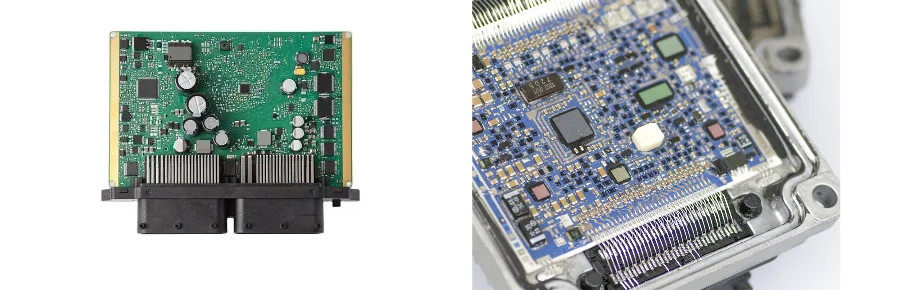
With the rapid growth of electric vehicles (EV) and Advanced Driver Assistance Systems (ADAS), power electronics are evolving toward higher power density, higher efficiency, and higher switching frequency. Silicon carbide (SiC) power devices, with their outstanding performance, have become the core of high-power inverters and power modules. However, SiC’s ultra-fast switching behavior (very high dV/dt and dI/dt) also brings unprecedented challenges to gate-driver printed circuit board (PCB) design. This guide dives into SiC inverter gate driver PCB best practices, helping engineers address thermal management, high-current paths, signal integrity, and manufacturability—so the final product meets automotive-grade reliability and high-voltage safety requirements.
Key challenges: strict requirements driven by SiC high-speed switching
SiC MOSFETs switch an order of magnitude faster than traditional silicon IGBTs, with rise/fall times typically in the nanosecond range. While this reduces switching loss and boosts efficiency, it also magnifies the negative impact of parasitics. In gate-driver PCB design, the main challenges stem from:
- Parasitic Inductance: In the gate-drive loop and the power commutation loop, even small inductance can create significant voltage overshoot under high dI/dt (V = L * dI/dt). This may damage SiC devices and also cause gate-voltage ringing or even false turn-on—posing a serious threat to SiC inverter gate driver PCB reliability.
- Parasitic Capacitance: Capacitance between devices, traces, and traces-to-ground planes can create common-mode currents under high dV/dt, driving EMI issues. It can also couple into the gate through Miller capacitance (Cgd), causing crosstalk and false triggering.
- Localized heat: Even though SiC is highly efficient, in MW-class inverter applications heat generation remains highly concentrated. If heat is not removed efficiently, junction temperature (Tj) rise will severely impact device lifetime and system reliability.
Therefore, a successful SiC inverter gate driver PCB must consider coupled multi-physics effects—electrical, magnetic, thermal, and mechanical—at the system level.
Thermal design: system-level heat management from TIM to Cold Plate
Efficient thermal management is the foundation for long-term stable operation of SiC inverters. The goal is a low thermal-resistance path from SiC junction temperature to the final cooling medium.
Selecting PCB base materials
Traditional FR-4 is cost-effective, but its thermal conductivity (~0.25 W/m·K) is often insufficient for high power-density SiC applications. Selecting the right SiC inverter gate driver PCB materials is critical:
- High-thermal FR-4 (High-Tg): Suitable for lower power density, using many Thermal Vias to conduct heat to the PCB backside or internal heat-spreading planes.
- Metal core PCB (MCPCB): Circuit layers are built on a highly thermally conductive metal base (typically aluminum or copper) separated by a thin insulating dielectric. This greatly reduces through-thickness thermal resistance and is well suited for direct mounting of power devices. HILPCB has strong experience in Metal Core PCB manufacturing and can support your design.
- Ceramic PCB: Uses ceramics such as Al2O3, AlN, or Si3N4, offering excellent thermal conductivity, high dielectric strength, and CTE close to SiC chips—an ideal choice when maximum performance and reliability are required.
System-level thermal solution integration
The PCB is only one part of the thermal path. In automotive-grade applications, it usually needs to work with more powerful thermal structures:
- Thermal Interface Material (TIM): Fill micro air gaps between SiC devices and the PCB, and between the PCB and the heatsink, using high-thermal-conductivity TIM (thermal grease, phase-change materials) to reduce contact thermal resistance.
- Heat Spreader/Sink: A large copper or aluminum heatsink is typically attached to the backside of the PCB, dissipating heat via natural convection, forced air, or liquid cooling.
- Cold Plate / Vapor Chamber (VC): For higher power levels, liquid-cooled cold plates are standard. The PCB design must consider mechanical interfaces, mounting hole locations, and flatness at contact surfaces to ensure efficient heat transfer.
Performance comparison of different SiC inverter gate driver PCB materials
| Material type | Thermal conductivity (W/m·K) | Relative cost | Primary application |
|---|---|---|---|
| High-Tg FR-4 | 0.3 - 0.5 | Low | Auxiliary power, low-power gate drive |
| Metal core PCB (IMS) | 1.0 - 7.0 | Medium | Mid-to-high power modules, DC/DC converters |
| Ceramic PCB (AlN) | 170 - 220 | High | Main inverter, power stage requiring extreme reliability |
High-current path optimization: co-designing busbar and Heavy Copper PCB
EV inverters can operate at hundreds of amps. Designing low-impedance, low-inductance high-current paths is another core challenge—directly impacting efficiency, EMI, and long-term reliability.
Using Heavy Copper PCB
To carry large current and support heat spreading, Heavy Copper processes are widely used.
- Current-carrying capability: Using 3oz or thicker copper significantly increases trace cross-sectional area, reduces DC resistance (I²R loss), and lowers temperature rise.
- Heat conduction: Thick copper layers act as effective heat spreaders, moving heat laterally to prevent localized hotspots. HILPCB’s Heavy Copper PCB service supports copper weight up to 12oz to meet the most demanding high-current applications.
Busbar integration
When current exceeds what PCB traces can handle, external busbars are required.
- Laminated Busbar: By laminating positive and negative copper bars with a thin insulating layer, you create a planar-capacitor structure with extremely low parasitic inductance—ideal for optimizing the power commutation loop. The PCB design should reserve connection pads or press-fit holes to interface with the busbar.
- PCB–busbar connection: Connection reliability is critical. Traditional bolted joints take space and can loosen. Press-fit is increasingly favored in automotive-grade applications due to high reliability, low contact resistance, and strong vibration resistance. It forms a gas-tight cold-weld joint by pressing specially designed terminals into precisely controlled plated holes.
Gate-drive loop layout: the key to minimizing parasitics and crosstalk
The gate-drive loop is one of the most detail-sensitive parts of SiC inverter gate driver PCB best practices. Any layout mistake can distort the drive signal and degrade system performance.
- Shortest-path principle: Place the gate driver IC as close as possible to the SiC device to minimize the physical length of the gate-drive loop (driver output → gate resistor → SiC gate → SiC source → driver ground).
- Minimize loop area: Loop inductance is proportional to loop area. Route the drive current path and return path tightly coupled and parallel—ideally on adjacent PCB layers—to leverage mirror-current effects and minimize loop inductance.
- Kelvin Connection: The SiC source is both the return node for the power loop and the reference for the gate-drive signal. Under high, fast-changing current, parasitic inductance on the source lead creates voltage drop that disturbs the gate reference. A separate Kelvin source connection ties the drive reference directly to the SiC chip source terminal, reducing common-source inductance coupling.
- Power decoupling: Place high-quality, low-ESL ceramic capacitors right next to the gate driver IC’s VCC and GND pins to provide a clean, low-impedance current path for fast gate charge/discharge.
Gate-drive layout essentials (SiC inverter gate driver PCB checklist)
- Proximity: place the driver IC close to the SiC device, within 2cm.
- Minimize the loop: tightly couple gate-drive forward and return paths and avoid large current loops.
- Kelvin connection: provide a dedicated source reference for the drive signal.
- Effective decoupling: place 0.1μF to 1μF low-ESL ceramic capacitors at the driver supply pins.
- Grounding: use a large, continuous ground plane for a stable return path and shielding.
- Isolation and creepage/clearance: ensure electrical clearance and creepage distances between the high-voltage side and low-voltage control side meet safety requirements.
Simulation and validation: a closed-loop flow for robust designs
Given the complexity of these design challenges, relying only on experience and design rules is not enough. A closed-loop “design–simulate–test” process is key.
Simulation-driven design
- EM simulation: During layout, use tools such as Ansys Q3D and Siwave to extract parasitics (R, L, C) for critical nets (gate-drive loop, power loop). Feeding these into circuit simulation tools (e.g., SPICE) enables accurate prediction of switching waveforms, overshoot, and ringing—so you can iterate and optimize before fabrication.
- Thermal simulation: Use tools like Flotherm and Icepak with device loss, PCB material properties, and thermal structures to predict temperature distribution, identify hotspots, and validate the cooling concept.
Rigorous physical testing
Simulation guides design, but physical testing is the final arbiter. A complete SiC inverter gate driver PCB testing plan is essential.
- Double-pulse test (DPT): The industry-standard method to characterize switching performance (turn-on/off energy, overshoot, ringing). Results can also validate simulation models.
- Thermal imaging: Under real load conditions, use an IR camera to capture temperature distribution on the PCB and power module to validate thermal design and compare against simulation.
- High-voltage and insulation test: Run Hi-Pot testing to ensure high-voltage isolation requirements are met for system safety.
- Environmental and reliability tests: Test prototypes under thermal cycling, vibration, and damp heat to evaluate long-term SiC inverter gate driver PCB reliability in harsh automotive environments.
To iterate quickly and validate designs, reliable prototyping is critical. HILPCB’s Prototype Assembly service can deliver high-quality PCBA fast, accelerating your R&D cycle.
DFM: from thick copper processing to press-fit terminal constraints
Even a theoretically perfect design is worthless if it cannot be manufactured economically and reliably. Therefore, DFM must be considered early.
- Heavy copper PCB DFM: Thick copper raises requirements for etching, lamination, and drilling. For example, undercut becomes more pronounced and may require larger line width/spacing; multilayer thick copper lamination needs tight resin-fill control to avoid voids.
- Press-fit hole DFM: Press-fit reliability depends heavily on hole size precision. Too large reduces contact force; too small can damage the barrel wall or the terminal. The manufacturer must have strict drilling and plating tolerance control.
- Assembly DFM: SiC power modules, large capacitors, busbars, and heatsinks often require special processes and equipment. Consider placement and access space for automated or manual assembly. Working with suppliers experienced in complex product assembly—such as those offering Box Build Assembly—helps ensure a smooth transition from PCB to finished product.
A detailed SiC inverter gate driver PCB checklist should include DFM items and drive early alignment with the PCB manufacturer.
HILPCB capabilities: protecting your SiC application
As a leading PCB solution provider, HILPCB understands the unique challenges of SiC applications. We offer:
- Advanced material processing: supports high-thermal materials, including metal core and ceramic substrates.
- Strong heavy-copper process: stable production up to 12oz heavy copper, with precise trace profile control.
- Strict tolerance control: high-precision PTH hole-size control for press-fit applications.
- Turnkey solution: from PCB fabrication to complex PCBA assembly, full-scope support.
Conclusion
In summary, SiC inverter gate driver PCB best practices is a multi-dimensional, system-level engineering challenge that requires the best balance across electrical performance, thermal management, mechanical structure, and manufacturability. The keys to success are: understanding the fundamental challenges brought by SiC high-speed switching; using a closed-loop validation flow that combines simulation and physical testing; and partnering early with an experienced PCB manufacturer.
By carefully optimizing the gate-drive loop layout, building an efficient system-level thermal path, designing reliable high-current interconnects, and addressing DFM from the start, you can truly unlock SiC’s potential and build safe, reliable ADAS and EV power systems that perform in harsh automotive environments. Choosing a professional partner like HILPCB can help you move faster and compete more effectively.
Common Questions
Why is a SiC gate driver PCB harder to design than a conventional silicon-based version?
Because SiC switches faster and exposes parasitic inductance, capacitance, loop layout, and isolation weaknesses much more aggressively. Details that were tolerable with silicon often become overshoot, ringing, false turn-on, or EMI problems in a SiC design.
Which risks should be contained first on a SiC gate driver board?
The biggest ones are usually gate-loop parasitics, coupling from the power stage, isolation and creepage control, thermal path design, and assembly variation around busbars or heavy-copper structures. The challenge is system closure, not just device selection.
What should be validated before a SiC inverter driver board is frozen for production?
Teams should focus on switching waveforms, overshoot and ringing, thermal distribution, insulation withstand, EMI behavior, and consistency after assembly. In automotive power electronics, a prototype that merely runs is only the beginning.
Why does manufacturability matter so early on SiC power boards?
Because tiny layout or process deviations can move electrical and thermal behavior in ways that are hard to recover later. Early DFM alignment helps keep the real hardware close to the simulated design window.