
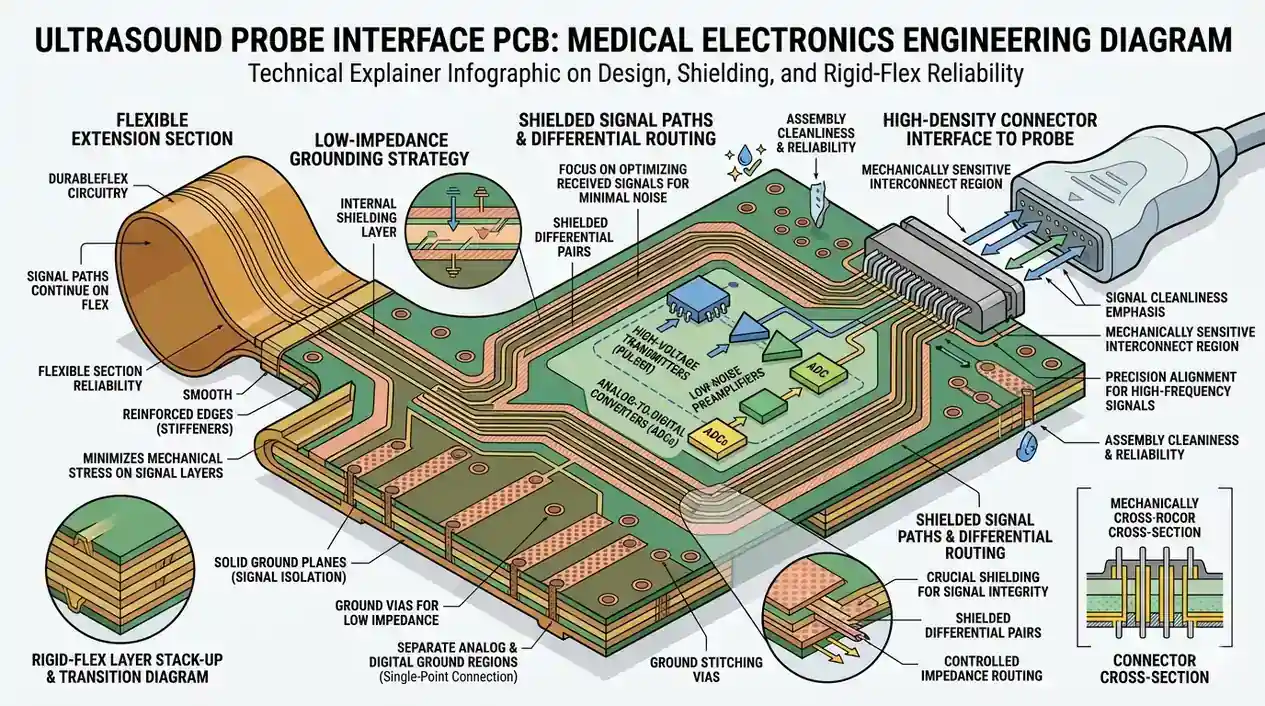
- An ultrasound therapy PCB should be reviewed as a medical electrical subsystem, not just as a power board or control board.
- The first engineering checks are isolation boundaries, applied-part signal paths, EMC-sensitive routing, thermal loading, and traceability expectations for assembly and test.
- Safety requirements do not come from a single PCB rule. They depend on the final device architecture, intended use, market, and how the probe, power stage, and enclosure interact.
- According to IEC 60601-1 and IEC 60601-1-2, the PCB layout directly affects basic safety, essential performance, and electromagnetic compatibility, so compliance risk often starts in stackup and placement.
- A stable launch usually requires the fabrication plan, assembly flow, inspection path, and regulatory evidence trail to be aligned before the first pilot build.
An ultrasound therapy PCB is the control, power, and interface electronics used inside ultrasonic physiotherapy equipment. It usually needs careful review of isolation, EMC behavior, thermal management, manufacturability, and traceability because the finished medical device must protect the patient, maintain essential performance, and survive regulated verification and production controls.
Contents
- What to review first on an ultrasound therapy PCB
- Key design and manufacturing rule table
- Early risk matrix for pilot builds
- How layout, stackup, and material choices affect safety and performance
- How assembly, traceability, and verification should be planned
- When to involve your PCB supplier and what to send
- FAQ
- Next steps
- References
- Author and review
What to review first on an ultrasound therapy PCB
An ultrasound therapy PCB is usually part of a larger electro-medical system that combines a power stage, control electronics, user interface, and a patient-coupled transducer path. It is not the same as a generic high-power driver board, and it should not be reviewed as if layout alone can "make it compliant." Compliance depends on the final device design, but the PCB often sets the boundary conditions for whether the rest of the system can pass.The first review points are usually:
- where patient-coupled or applied-part circuitry begins and how it is isolated from mains, charging, or higher-energy sections
- which nets are sensitive to switching noise, burst energy, or conducted and radiated interference
- whether heat from the drive stage, power conversion, and enclosure constraints can be removed without shifting component stress
- whether stackup, creepage path geometry, slotting, keep-out spacing, and shielding decisions can actually be fabricated and assembled repeatably
- how the project will maintain component traceability, test evidence, and build records if it moves from prototype to regulated production
For teams still refining board structure, it is often useful to review the fabrication route against multilayer PCB and high Tg PCB constraints before committing to a pilot layout.
Key design and manufacturing rule table
| Rule / parameter | What to check first | Why it matters | How to verify | If missed | | --- | --- | --- | --- | --- | | Isolation architecture | Separate patient-coupled, power, control, and I/O domains early | IEC 60601-1 safety strategy depends on insulation means, working voltage, and device architecture | Schematic partition review, creepage review, stackup review, enclosure review | Late redesign, unsafe coupling paths, failed safety evaluation | | EMC-sensitive routing | Keep switching loops, clock nets, and probe-interface paths intentionally separated | IEC 60601-1-2 EMC performance is strongly affected by return paths, shielding, and layout discipline | Placement review, return-path inspection, pre-compliance EMC planning | Noise coupling, unstable therapy output, immunity failures | | Thermal loading | Review MOSFETs, drivers, regulators, transformers, and hot copper zones as one heat system | Ultrasound therapy boards often combine burst power with enclosed mechanical packaging | Thermal simulation, copper review, prototype thermal measurement | Derating problems, drift, shortened component life | | Material and stackup fit | Confirm Tg, layer count, copper balance, and any controlled impedance or shielding need | Material behavior affects warpage, insulation stability, and signal behavior during assembly and use | Stackup signoff and fabrication DFM | Unstable builds, warpage, marginal noise behavior | | Assembly traceability | Decide how lot control, inspection, and build records will be captured | Medical production usually needs stronger process evidence than generic commercial electronics | Traveler definition, serial traceability plan, supplier quality review | Weak audit trail, harder root-cause analysis, slower regulatory support | | Test strategy | Define electrical, functional, and pre-compliance checks before pilot build | Some risks are invisible in bare-board inspection and only appear under powered conditions | DFT review, fixture planning, functional test definition | Defects escape to later stages or field evaluation |Early risk matrix for pilot builds
| Early signal | Typical root cause | Most affected area | Recommended action before pilot release | | --- | --- | --- | --- | | Isolation review is still schematic-only | Layout and enclosure teams have not frozen real physical boundaries | Safety and regulatory readiness | Freeze physical isolation paths, slots, keep-outs, and connector spacing before Gerber release | | Noise is treated as a firmware problem | Power stage, transducer drive, and analog sensing share poor return paths | EMC and therapy stability | Review grounding, loop area, shielding, and cable exit paths before assembly | | Thermal plan assumes airflow that may not exist | The board was optimized on bench conditions, not in the final enclosure | Reliability and output consistency | Validate heat rise in representative enclosure conditions during prototype build | | Build records are not defined | Prototype and production expectations are mixed together | Traceability and scale-up control | Decide early whether the board will move into regulated pilot or low-volume production and set records accordingly |How layout, stackup, and material choices affect safety and performance
Most ultrasound therapy PCB problems appear where safety, EMC, and power density overlap. According to IEC 60601-1, the finished medical electrical equipment has to maintain basic safety and essential performance. According to IEC 60601-1-2, it also has to tolerate electromagnetic disturbance while limiting emissions. That means the board should be designed around separation, current return control, and predictable field behavior rather than only around schematic connectivity.Three areas usually matter first.
1. Isolation and physical partitioning
If the product includes mains input, external adapters, batteries, probe interfaces, communication ports, or treatment outputs, the board should make those boundaries visible in both schematic and layout. Creepage and clearance are not one fixed number for all products. They depend on the working voltage, insulation strategy, pollution assumptions, applied-part classification, and the final enclosure system. A useful engineering step is to review the finished boundary in a Gerber viewer before release rather than assuming the CAD screenshot is enough.
2. EMC and signal containment
Therapy boards often mix switching power, waveform generation, sensing, UI control, and external cables. Those functions can interfere with one another if loop areas are large or if analog and high-energy paths are forced through the same return structure. If the design includes dense routing, shielding structures, or layered reference planes, a multilayer PCB stackup review should happen before fabrication files are frozen.
3. Thermal margin and long-term stability
The transducer drive stage and associated power conversion can create local hot zones, especially in compact housings. The right answer is not always "use thicker copper." Sometimes the board needs better copper distribution, thermal vias, component relocation, or a more stable resin system for repeated heat exposure during assembly and operation. For boards that run hotter or see longer soldering cycles, high Tg PCB or high thermal PCB options may be worth reviewing as project-specific decisions rather than default assumptions.
How assembly, traceability, and verification should be planned
For medical electronics, a good bare-board design is only one part of the release path. Assembly control, inspection evidence, and traceability planning usually determine whether the board can move cleanly from prototype into a documented manufacturing flow.ISO 13485 focuses on quality-management controls for medical-device production, and ISO 14971 frames risk management across the product lifecycle. In practice, that means the PCB team should align with assembly and quality teams on what needs to be recorded, inspected, and reviewed before production is scaled.
A practical manufacturing plan usually includes:
- Prototype build intent defined early
Decide whether the build is for electrical learning, enclosure fit, verification, or a documented pilot. That changes the inspection and record depth required. - Controlled component and revision handling
Critical BOM items, firmware versions, and substitute rules should be visible before assembly release. A BOM viewer can help teams review line-item consistency before purchasing and build prep. - Inspection and functional test path
AOI, X-ray, flying-probe, ICT, or functional test should be chosen based on the board's actual risk profile, not just on standard house routing. - Process documentation for pilot builds
Traveler records, serial control, rework boundaries, and acceptance criteria should be defined before the first regulated pilot, not reconstructed later.
If the project needs coordinated sourcing, fabrication, and assembly, SMT assembly, turnkey assembly, and PCB prototype support are usually more useful than treating fabrication and PCBA as disconnected purchases.
When to involve your PCB supplier and what to send
Ultrasound therapy boards usually benefit from supplier review before layout freeze, not after a failed prototype. The highest-value handoff is the one that lets fabrication, assembly, and test planning happen while changes are still cheap.The most useful package usually includes:
- schematic or system block diagram showing isolation boundaries
- preliminary stackup target and board thickness assumptions
- Gerber or native layout data for spacing, copper, and shielding review
- BOM with critical components and approved alternatives clearly marked
- assembly drawings, test intent, and enclosure constraints
- any known market, compliance, or documentation requirements already defined by the OEM
If the board is still in DFM review, a quick-turn build through PCB prototype or quick-turn PCB is often the fastest way to validate spacing, solderability, thermal behavior, and test access before the design is locked. If the package is ready for commercial review, the cleanest next action is usually a quote request.
FAQ
Is an ultrasound therapy PCB always classified the same way in every market?
No. Device classification depends on jurisdiction, intended use, claims, and final product configuration. The PCB should be designed to support the target device strategy, but classification decisions belong to the finished medical product and its regulatory pathway.
Does passing a bare-board DFM review mean the medical device is compliant?
No. DFM review helps prevent fabrication and assembly problems, but compliance depends on the finished device, including enclosure, power architecture, cables, software, risk controls, and verification results.
Why is EMC such a big issue for ultrasound therapy boards?
Because these boards often combine switching power, waveform generation, sensing, and external interfaces in one system. Poor return-path control or cable routing can affect both emissions and immunity performance.
Should medical ultrasound boards always use special materials?
Not always. Material choice depends on thermal load, mechanical constraints, voltage stress, assembly process, and reliability targets. The correct material is a project decision, not a generic rule tied only to the word "medical."
What should be frozen before sending the board to pilot assembly?
Freeze isolation intent, stackup assumptions, major placement constraints, critical BOM items, test strategy, and the level of traceability expected for the pilot build.
Next steps
If you are building an ultrasound therapy device, the most useful next step is usually to review the board as part of the whole medical electrical system rather than as an isolated PCB file.HILPCB can support that review through:
- Multilayer PCB planning when shielding, reference planes, and dense routing need to stay controlled
- High Tg PCB or high thermal PCB review when the drive stage or enclosure raises thermal stress
- SMT assembly and turnkey assembly alignment when build control, traceability, and pilot execution need to stay coordinated
- PCB prototype and quick-turn PCB support for early verification builds
- Request a quote when your layout, BOM, and assembly package are ready for review