
A power via array is ready for a current claim only after the complete transition has been assessed under the intended load, temperature and cooling conditions. Equal-sized vias do not necessarily carry equal current: the copper feeding each via, the receiving plane and the return path all matter.
For an initial barrel-area and ideal-resistance calculation, use the PCB via current capacity guide and its calculator. The checks below focus on what that ideal calculation cannot establish: the resistance between defined board locations, current crowding and temperature in the assembled system.
1. Define the Path Before Counting Vias
Identify where load current enters and leaves the transition. The path includes the source-side copper, pads, via segments and receiving copper; the other side of the supply loop needs its own assessment. The relevant barrel length is the portion carrying the current between connected layers, not automatically the full finished board thickness.
Record the following before comparing layouts:
| Input | Define for the actual design |
|---|---|
| Load | Continuous and transient waveforms, simultaneous loads, and the relevant supply and return paths |
| Electrical boundary | Locations of current terminals and voltage-sense points, including any connectors or copper necks included in the budget |
| Construction | Finished hole dimensions, specified hole-wall copper, connected layers, pad and plane geometry, and tolerances |
| Thermal boundary | Local ambient, nearby heat sources, enclosure, airflow, mounting and allowable component or material temperatures |
| Acceptance | Permitted drop and temperature at specified locations, measurement uncertainty, and the responsible design authority |
The manufacturer can review whether the requested board features are feasible and inspect the specified construction. The system designer must set electrical and thermal limits and qualify the populated assembly in its operating environment.
2. Why Does a Parallel Array Share Unevenly?
If identical barrel resistances connect the same two ideal equipotential nodes, each carries the same DC current and their equivalent resistance is one barrel resistance divided by the number of vias. On a real board, copper has resistance too: the potential at each via entrance and exit can differ. Nominally identical barrels alone do not guarantee equal sharing.
| Layout condition | What can change | What to inspect |
|---|---|---|
| A long array fed from one end | Access resistance differs along the array | Copper width and the actual source and load positions |
| Narrow pad neck or plane corridor | The shared copper limits current before it reaches the array | Neck width, copper thickness and antipad clearance |
| Relief spokes | Each plane connection adds resistance and changes heat flow | Spoke geometry, count and manufacturing requirements |
| Dense cluster | Vias can heat the same surrounding copper and substrate | Complete array temperature under simultaneous load |
| Different barrel construction | Resistance and current sharing can vary | Hole size, plating distribution and connected length |
The Siemens via-array study models unequal DC currents for specific plane and via geometries. Its results are simulations of those structures, not measured branch currents or a universal sharing factor. For a critical path, model the actual entry and exit copper with the via network, then validate the resulting design.
3. Compare an Estimate With a Measured Transition
Consider a hypothetical prototype with four identical barrel segments. At a specified copper temperature, suppose each segment has an estimated resistance of 1.2 milliohms. If the endpoints were ideal equipotential nodes and each segment shared current equally, their combined barrel resistance would be 0.30 milliohms. At 8 A, the ideal barrel-only drop would be 2.4 mV and total barrel loss would be 19.2 mW.
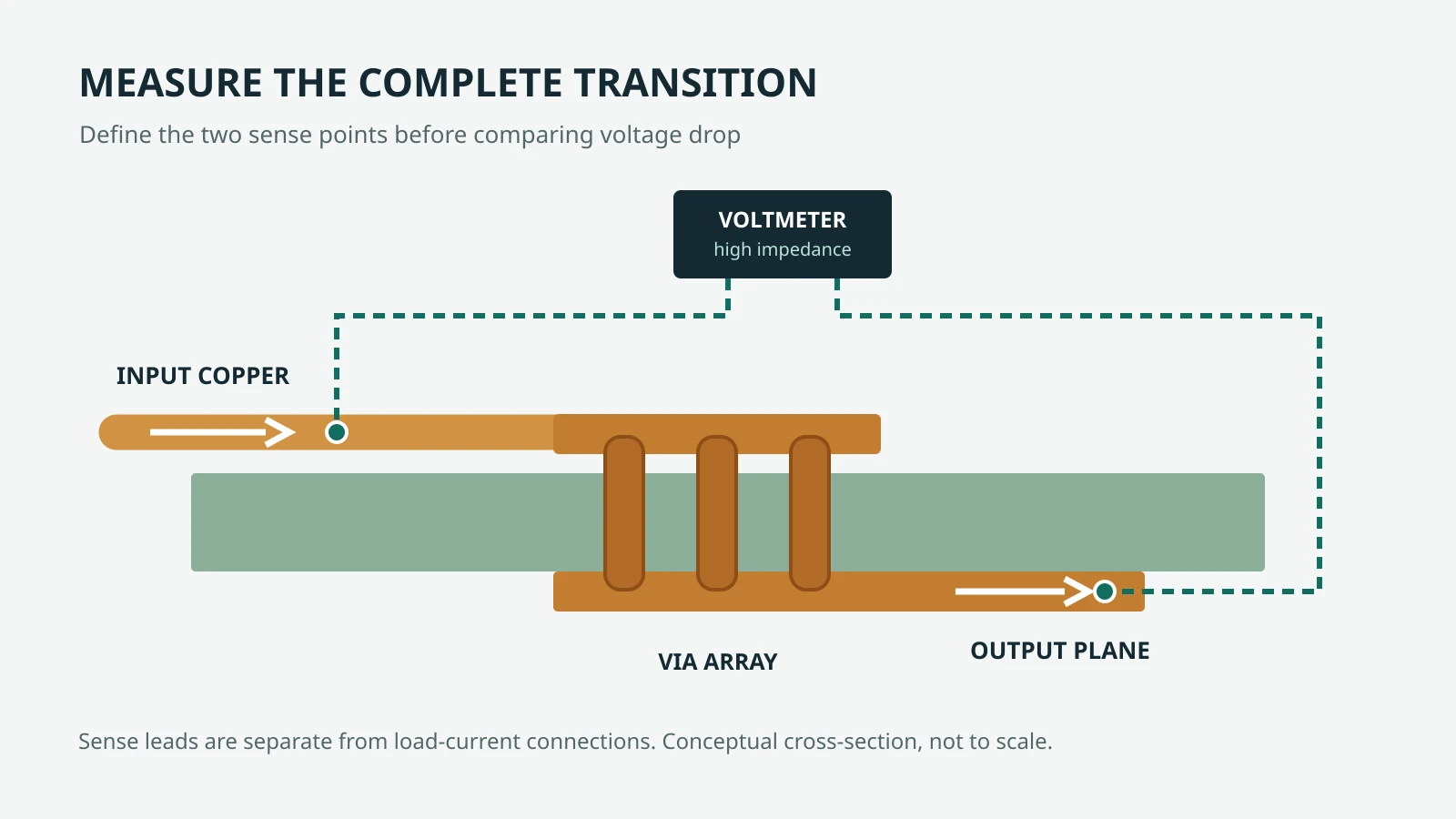
Now suppose a four-wire measurement reads 6.4 mV at the same 8 A between marked points on the input copper and receiving plane. The measured resistance of that defined transition is 6.4 mV / 8 A = 0.80 milliohms; the voltage-drop product is 51.2 mW for the section between those points. The hypothetical measurement includes every conducting feature between the sense points, including access copper and connections. It does not locate a hotspot, reveal individual via currents or prove that the array meets a temperature limit.
The 0.80 milliohm measurement and 0.30 milliohm barrel-only estimate have different boundaries. Their difference is not a measured resistance of any one feature: the ideal equal-sharing assumptions, copper temperatures, geometry and measurement uncertainty all affect the comparison. Record the points, current, temperature, instrument resolution and polarity so a second test can reproduce it. A DC result alone does not characterize fast transient behavior.
4. Measure Voltage Drop With Defined Sense Points
Use a suitable current source or operating load and a voltmeter with adequate resolution for the expected drop. A four-wire arrangement separates the load-current connections from the voltage-sense leads, reducing the effect of load lead and contact resistance outside the sense points. It does not remove resistance within the chosen section.
- Mark the input and output sense locations on the design and confirm that they are accessible without disturbing the assembly. An inner plane may require a designed test access or coupon; a nearby surface pad can include extra copper and via resistance.
- Connect the current path and sense leads according to the test equipment and circuit limits. Check polarity, current rating and safe operating conditions before applying power.
- Record ambient and relevant board temperatures, current waveform, operating mode and meter range. For a steady DC comparison, allow conditions to stabilize according to the test plan.
- Measure the voltage between the marked points and the actual current. Divide the measured DC voltage by the measured DC current to report the resistance of that defined section. Include measurement uncertainty and any offset correction in the report.
- Compare repeated runs and representative samples at the specified load and environmental conditions. If the drop exceeds its budget, investigate the access copper, connections and array together before deciding which feature to change.
Do not infer the current in each via from a single end-to-end voltage reading. Separating branch currents requires an appropriate validated measurement or model for that layout; adding a probe or test structure can itself change the current path.
5. Test Temperature in the Intended Assembly
Voltage drop and temperature answer different questions. Copper loss contributes heat, but the steady temperature also depends on heat spreading, neighboring components, mounting and ambient conditions. A low millivolt drop by itself does not establish an acceptable hot-spot temperature.
The Brooks and Adam test illustrates this dependence: its particular test boards had different local via-area temperatures with different trace widths. The published setup and sensor location limit what can be inferred about the barrel itself. Those observations are not a rating for another construction.
For a prototype test, define the load, supply and return paths, enclosure, ambient measurement position, airflow and stabilization criterion. Record temperatures at accessible risk locations and note sensor placement and calibration. An infrared camera can help find accessible surface hotspots, but surface emissivity, reflections and the field of view affect the reading; it cannot directly measure a buried barrel. Use suitable contact sensors or representative test structures when the critical location is inaccessible. Check both temperature rise and absolute temperature against the project's defined limits.
| Test record | Example field to retain |
|---|---|
| Board and revision | Stackup, fabrication lot and assembly configuration |
| Operating case | Current, duration, switching or DC condition, nearby loads |
| Environment | Ambient sensor position, enclosure, mounting and airflow |
| Electrical | Sense-point coordinates, measured current, voltage and instrument uncertainty |
| Thermal | Sensor type and locations, highest observed temperature, time and stabilization criterion |
| Disposition | Applicable limits, reviewer, anomalies and follow-up action |
6. Check Faults and Manufacturing Separately
Continuous-current tests do not establish fault survival. For inrush, overload or a short circuit, document the actual current waveform, initial temperature, protection device tolerances, total clearing behavior and current paths. Fuse melting and total clearing I²t are different quantities. I²t alone is not the energy absorbed by a via array and does not prove that a particular board will survive. Evaluate the circuit with the device supplier's current data and an appropriate engineering test plan; use protected test equipment and qualified personnel.
Ask the fabricator to confirm the drawing's applicable standard revision, finished-hole requirements, hole-wall copper definition, inspection method, layer connections and any filled or capped via requirements. Do not equate external copper weight with hole-wall plating, or a specified average with a guaranteed minimum at every point. The microsection guide explains the role of sectioning; agree the sampling and acceptance criteria for the actual order.
Before release, give the fabricator the stackup, drill files, copper layers, connection details and critical-net notes. Use the multilayer PCB service and a quote request to discuss the proposed construction. Board fabrication review does not replace system-level current, thermal or fault qualification.
FAQ
Can I assume one via per amp?
No universal via count per amp establishes a safe design. Current sharing, barrel and connection geometry, temperature, operating environment and the project's acceptance limits must be evaluated together.
Does measuring array voltage drop show the current in each via?
No. The measurement gives the voltage between its two sense points. Together with total DC current it gives the resistance of that defined section, but not a unique current for each barrel.
Where should the voltage-sense points go?
Place and document them at the boundaries of the transition being evaluated, with separate sense leads where practical. If an inner layer cannot be contacted directly, account for the additional connection or use a suitable test structure.
Can thermal relief spokes be used on power vias?
They may be appropriate in some constructions, but their electrical and thermal effects depend on the actual geometry and manufacturing needs. Evaluate the complete path and agree the connection style with the fabricator.
Does a fuse guarantee that the via array survives a short circuit?
No. Evaluate the fault waveform, current paths, initial temperature, protection tolerances and total clearing behavior for the actual circuit. A single fuse I²t value does not establish via survival.