
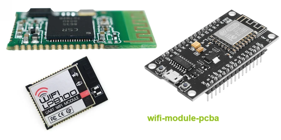
A Wi-Fi module PCB integrates a radio, RF front end, clocks and supporting circuitry into a qualified subassembly that a host product must power, route, cool, connect to an antenna and validate correctly. Module integration reduces radio design scope, but it does not make antenna performance, coexistence or end-product certification automatic.
Key Takeaways
- Select the module from bands, host interface, software/security lifecycle, antenna, temperature and approval conditions.
- Copy the vendor's land pattern, antenna keep-out, host ground and RF geometry as controlled reference data.
- A 50-ohm feed is a stackup-dependent transmission line. Trace width alone does not prove impedance through pads, bends, vias, switches or connectors.
- Keep copper and mechanical objects out of the specified antenna volume; do not infer range from S11 alone—validate OTA performance in the enclosure.
- Wi-Fi/Bluetooth/Zigbee coexistence needs spatial, frequency and time-domain controls plus desense testing under simultaneous traffic.
- Pre-certification helps only while antenna, layout, firmware, labeling and host conditions remain within the module's instructions and grant.
- FR-4 can suit short RF feeds; select lower-loss material from the complete loss and production budget.
Table of Contents
- Freeze the Wireless Product Requirements
- Choose Module, Chip-Down and Antenna Architecture
- Implement the Antenna and RF Feed
- Place the Module on the Host PCB
- Design Power, Ground and Thermal Paths
- Route Host Interfaces Without Creating Desense
- Plan Multi-Radio Coexistence
- Preserve Module Certification Conditions
- Use a Wi-Fi Module Release Matrix
- Diagnose Common Integration Failures
- Wi-Fi Module PCB RFQ Checklist
- Reference Standards and Responsibility Boundaries
- How HILPCB Supports Wireless Builds
- FAQ
- Conclusion
Freeze the Wireless Product Requirements
“Add Wi-Fi” is not a module specification. Record the operating and lifecycle requirements before comparing data sheets.
| Requirement | Questions that change the hardware |
|---|---|
| Radio | Which 2.4, 5 or 6 GHz bands and channel widths are legal and required in each market? |
| Performance | Throughput, latency, range, roaming, load profile and simultaneous-client behavior? |
| Host and power | Interface, voltage, boot, driver/OS, peak current, ripple and sequencing? |
| Antenna | Integrated, external or MIMO/diversity; what enclosure volume is available? |
| Coexistence | Which Bluetooth, Thread/Zigbee, cellular or GNSS radios can transmit simultaneously? |
| Environment/lifecycle | Temperature, mechanics, user proximity, module availability and firmware maintenance? |
| Compliance | Countries, grants, permitted antennas/gains, labeling and host tests? |
Wi-Fi 6E extends Wi-Fi operation into the 6 GHz band where permitted; available channels and power rules vary by country and device class. A hardware SKU and firmware region configuration must not enable an unauthorized combination.
Choose Module, Chip-Down and Antenna Architecture
Modules trade layout freedom and unit cost for reduced RF design scope and a documented integration path.
| Architecture | Main advantage | Main constraint | Best fit when |
|---|---|---|---|
| Module with integrated antenna | Shortest RF path and a characterized antenna implementation | Host edge position, keep-out and enclosure strongly constrained | Space supports the vendor's exact antenna conditions |
| Module with RF connector | Antenna can be moved away from noisy or shielded electronics | Cable, connector, antenna approval and assembly become critical | Enclosure provides a better remote antenna location |
| Module with RF pin to host antenna | Host can select PCB, chip or external antenna | Feedline and antenna tuning become host responsibilities | Industrial design requires a custom antenna location |
| Chip-down radio | Maximum size/BOM/layout optimization | RF matching, calibration, shielding and certification burden | Volume and engineering resources justify full RF ownership |
Do not select a module only from the peak PHY rate. Throughput depends on antennas, spatial streams, channel conditions, protocol overhead, host interface, driver, CPU and power/thermal limits.
Implement the Antenna and RF Feed
An antenna data sheet is valid for a defined ground plane, clearance, feed and test environment. The final host changes all four.
For an integrated module antenna, place the antenna end at the host-board edge or project it beyond the board when the vendor instructs. Apply the stated keep-out on every copper layer and extend it to components and mechanical objects. A battery, display frame, shield can, cable, metal fastener or conductive coating near the antenna can detune it or reshape the pattern.
For a host antenna, route a controlled 50-ohm structure over a continuous reference plane. Calculate it from the production stackup, finished copper and solder-mask model. Keep the feed short, avoid stubs, and preserve the return at layer transitions with nearby ground vias when the reference design requires them. Matching-component footprints should be placed in the same topology and orientation used by the antenna supplier.
| Antenna evidence | What it proves | What it does not prove |
|---|---|---|
| VNA S11/return loss | Match and resonance at the measurement plane | Radiation efficiency, pattern, receiver sensitivity or range |
| Radiation efficiency/gain | How accepted power is radiated and distributed | Receiver implementation or protocol throughput |
| TRP | Transmit performance integrated over direction | Receiver sensitivity |
| TIS | Receiver performance integrated over direction | Transmit performance |
| Conducted RF test | Radio output, modulation and receive behavior without antenna uncertainty | Installed antenna performance |
An S11 result can look good because energy is lost in dielectric, matching parts or nearby material rather than radiated. Use OTA evidence for the final product.
Place the Module on the Host PCB
Treat the module land pattern and ground implementation as controlled geometry. Use the current module hardware integration guide and its reference files.
- Keep prohibited host signals, slots and plane splits out from under the module; use the specified ground pad, paste and vias.
- Keep the required continuous ground plane below the module and route host signals deeper.
- Preserve test, calibration, reset, boot and programming access.
- Document shield height, mechanical keep-outs and rework access.
MIMO or diversity antennas require more than distance. Orientation, coupling, enclosure modes and correlation affect performance. Use the module supplier's reference arrangement as the starting point and validate the actual product in an OTA chamber.
Design Power, Ground and Thermal Paths
Transmit bursts expose rail impedance. Follow the vendor regulator and decoupling design, keep capacitor supply/return paths short, and measure droop at the module. Avoid generic RF/digital ground splits; reference designs commonly require continuous ground, with noise controlled by placement, returns and filtering.
Ground pads and vias transfer heat, but enclosure and airflow set final temperature. Measure sustained transmit and coexistence at maximum ambient; a shield may spread heat while reducing convection.
Route Host Interfaces Without Creating Desense
SDIO, PCIe, USB, clocks and switch-mode regulators can create in-band harmonics. Route each interface to specification over continuous reference, keep fast edges away from the antenna/feed, and test receiver sensitivity while interfaces, displays, memory and regulators run worst-case workloads. Include mounting inductance and regulator behavior in the PDN review.
Plan Multi-Radio Coexistence
The 2.4 GHz band commonly carries Wi-Fi, Bluetooth and Thread/Zigbee traffic. Cellular transmitters can desensitize Wi-Fi or GNSS through harmonic, intermodulation, power and antenna coupling paths.
| Control domain | Examples | Validation |
|---|---|---|
| Spatial | Antenna separation, orientation, shielding and ground-current control | Coupling S-parameters and OTA patterns in final mechanics |
| Frequency | Band selection, channel planning, SAW/BAW/diplexer filtering | Blocking/desense sweep across operating bands |
| Time | PTA/coexistence interface, grants, priorities and firmware scheduling | Simultaneous traffic with latency/throughput acceptance limits |
| Power | Transmit-power backoff and mode-specific limits | Performance versus power, thermal and regulatory constraints |
| System | Cable/chassis bonding, regulator synchronization and clock planning | Worst-case product workload and installation state |
Packet Traffic Arbitration helps only when hardware signals, logic levels, timing and firmware policy are implemented as the module vendor specifies. It cannot fix severe antenna coupling or an overloaded receiver front end.
Preserve Module Certification Conditions
“Pre-certified” means the module was approved in a documented configuration. The integrator must review the grant and instructions for:
- permitted antenna types and maximum gain;
- RF trace or connector conditions;
- separation/exposure and simultaneous-transmitter conditions;
- shielding, power, approved firmware and regulatory-domain control;
- labeling, user instructions and required end-product tests.
A different antenna, higher gain, changed RF path, co-located transmitter or portable exposure condition may require additional assessment or a permissive change. Regional approvals are not interchangeable. Keep the module's certification documents, antenna BOM and firmware configuration under revision control.
Use a Wi-Fi Module Release Matrix
| Release gate | Controlled input | Evidence required | Reject when |
|---|---|---|---|
| Selection/schematic | Bands, host, antenna, software, power, boot and approvals | Compliance matrix plus vendor checklist | Market, lifecycle, sequencing or test access is unresolved |
| Layout | Land pattern, stackup, keep-out, feed, reference plane and mechanics | Overlay against reference files plus DFM | Antenna volume or ground condition is violated |
| Prototype | Released BOM, enclosure and firmware | Power, interface, conducted RF, VNA and desense data | Reset, sensitivity loss or unstable calibration appears |
| Certification | Production-intent mechanics, antennas and software | OTA, emissions, exposure and regional evidence as applicable | Test sample differs materially from released product |
| Pilot | Approved module lot, paste/reflow and end-of-line test | Yield, RF check, programming and traceability | Substitution or process drift lacks disposition |
Archive chamber setup, cable loss, calibration, antenna orientation, firmware, regulatory domain, traffic profile and sample revision. RSSI screenshots without a controlled peer and geometry are weak comparison evidence.
Diagnose Common Integration Failures
| Symptom | Likely causes | Next discriminating test |
|---|---|---|
| Good conducted RF, poor range | Detuned/inefficient antenna, enclosure loss or pattern null | OTA TRP/TIS and pattern versus open-board baseline |
| Throughput collapses during Bluetooth use | Antenna coupling, missing PTA, filter limit or policy | Simultaneous traffic with coexistence signals and RF isolation data |
| Module resets on transmit | Rail droop, sequencing, thermal or firmware watchdog | Probe voltage at module during burst; log reset cause |
| Receiver sensitivity changes with display/CPU load | Clock/regulator/interface harmonic desense | Conducted sensitivity while enabling aggressors one at a time |
| Certification result differs from module grant | Antenna, RF path, power, firmware or co-location condition changed | Grant-to-host integration compliance audit |
Wi-Fi Module PCB RFQ Checklist
Module/wireless: exact part/revision, integration guide, firmware/driver, countries, bands, antennas, output power, performance goals, coexistence cases and approved alternates.
PCB/mechanics: schematic, Gerber/ODB++/IPC-2581, stackup, impedance geometry, land pattern, keep-outs, RF feed/matching, ground vias, paste, enclosure CAD, battery/display/cables, shields and user proximity.
Test/compliance: conducted RF and VNA access, tuning parts, TRP/TIS and desense goals, fixtures, programming, module grants, approved antenna list, exposure/labeling, regional tests, traceability, reflow/moisture handling and change triggers.
Reference Standards and Responsibility Boundaries
- IEEE 802.11 — IEEE
- Wi-Fi Alliance certification programs — Wi-Fi Alliance
- FCC 47 CFR Part 15 — FCC
- FCC KDB 996369 — FCC
- ETSI EN 300 328 — ETSI
- ETSI EN 301 893 — ETSI
- ETSI EN 303 687 — ETSI
- RED 2014/53/EU — European Union
- IEC 62368-1 — IEC
- IPC-2221 — IPC
- IPC-6012 — IPC
- IPC-A-610 — IPC
Requirements vary by country, band, power, antenna, exposure condition and product class. HILPCB can manufacture controlled stackups, RF feeds, keep-outs and module assemblies and can support DFM and test access. The module supplier owns its declared module design and grant; the product owner remains responsible for host integration, firmware/regulatory configuration, antennas, coexistence, exposure, labeling and final end-product compliance.
How HILPCB Supports Wireless Builds
HILPCB can review module footprint, paste openings, ground vias, antenna keep-out, RF-feed geometry, stackup, reference continuity, matching access and mechanical constraints before fabrication. High-frequency PCB manufacturing is available when the loss and tolerance budget requires a qualified RF material, while multilayer PCB manufacturing supports continuous reference planes and dense host routing.
For validation units, small-batch PCB assembly can preserve module revision, antenna/matching BOM and inspection traceability. Exact impedance tolerance, material, reflow, module handling and RF test scope are confirmed per quotation.
FAQ
Does a pre-certified Wi-Fi module eliminate product certification?
No. It may reduce intentional-radiator work when the host follows the grant and integration instructions. The final product can still require emissions, exposure, labeling, regional, co-location and safety evaluation.
How large should the Wi-Fi module antenna keep-out be?
Use the exact current module or antenna reference design. There is no universal distance: antenna type, ground plane, frequency, enclosure and mechanical objects determine the required all-layer and three-dimensional clearance.
Is a 50-ohm antenna trace enough to guarantee good Wi-Fi range?
No. It controls one feedline property. Range also depends on mismatch, radiation efficiency, pattern, receiver sensitivity, transmit quality, enclosure, interference, protocol and environment. Validate conducted RF and OTA performance.
Does Wi-Fi 6E require a Rogers PCB material?
Not automatically. A short, controlled feed on characterized FR-4 may meet its loss and tolerance budget. Longer feeds, tighter repeatability, filters or demanding antennas may justify lower-loss material. Decide from the complete RF path and production variation.
Conclusion
A Wi-Fi module is a starting boundary, not a finished wireless product. Send HILPCB the module reference files, host stackup, antenna and mechanical package, coexistence requirements, certification conditions and test plan so the fabricated and assembled host preserves the configuration that RF validation will qualify.