
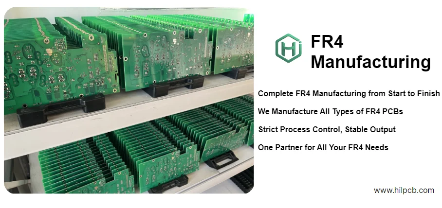
- FR4 is the standard glass-reinforced epoxy laminate used for many general-purpose PCBs, but it is not the right answer for every stackup.
- The first checks are Tg, dielectric consistency, moisture behavior, thermal exposure, mechanical needs, and whether the design has real high-speed or RF loss limits.
- Many FR4 selection mistakes come from treating all FR4 grades as identical, even though resin systems and electrical behavior can vary meaningfully by product family.
- FR4 is usually a good fit for mainstream digital, control, industrial, and consumer boards when the electrical and thermal margins are realistic.
- If the design has tighter loss, RF, thermal, or dimensional-stability demands, the material review should happen before impedance targets and fabrication rules are frozen.
FR4 is a glass-fiber reinforced epoxy laminate widely used for rigid printed circuit boards. It is popular because it balances mechanical strength, insulation, manufacturability, and cost, but its actual performance depends on the specific laminate system, Tg grade, and the electrical, thermal, and reliability demands of the finished design.
Contents
- What to review first when selecting FR4 material
- Key material and design rule table
- Early engineering trade-off table
- How FR4 behaves in stackup, impedance, and thermal planning
- When FR4 is enough and when another material should be reviewed
- What fabrication and prototype teams should confirm before release
- FAQ
- Next steps
- References
- Author and review
What to review first when selecting FR4 material
FR4 is often treated like a generic commodity, but in engineering terms it is a material family, not one exact electrical profile. That matters because stackup control, impedance prediction, thermal survival, and reliability all depend on the actual laminate system the project will use.
The first review points are usually:
- which Tg range and resin system the fabrication route expects
- whether the design needs ordinary digital performance or tighter dielectric consistency for higher-speed work
- how much soldering heat, field temperature, or rework exposure the board will see
- whether moisture uptake, dimensional stability, or CAF-related reliability concerns matter for the end use
- whether the design would be better served by a different material class for RF, very low loss, or high thermal demands
For designs that already know they need tighter electrical control, it is often better to compare FR4 against high-speed PCB, high-frequency PCB, or Rogers PCB routes before the stackup is locked.
Key material and design rule table
| Rule / parameter | What to check first | Why it matters | How to verify | If ignored | | --- | --- | --- | --- | --- | | Tg grade | Confirm whether standard, mid-Tg, or high-Tg FR4 fits the process and use condition | Glass-transition behavior affects thermal stability and assembly margin | Laminate datasheet review and fabrication stackup signoff | Warpage, weaker thermal margin, rework sensitivity | | Dielectric behavior | Use the actual laminate data for stackup and impedance planning | FR4 electrical behavior varies by resin system and frequency | Stackup review and [impedance calculator](/tools/impedance-calculator/) check | Impedance miss and inconsistent SI behavior | | Loss tolerance | Decide whether ordinary FR4 loss is acceptable for the actual channel budget | High-speed and RF channels may need lower-loss materials | Channel review and insertion-loss budget | Marginal signal quality or redesign | | Moisture and reliability exposure | Review storage, environment, and long-term field conditions | Moisture and environmental stress can affect reliability and assembly behavior | Reliability review, handling plan, prototype validation | Latent reliability risk and variable yield | | Thermal load | Review copper, power density, and assembly cycle demand together | Material selection is linked to both field use and manufacturing stress | Thermal review and fabrication DFM | Delamination risk, warp, reduced life | | Fabrication fit | Confirm the chosen FR4 family is available in the thickness, copper, and build style required | Material planning has to match actual factory supply and stackup capability | Stackup approval and sourcing review | Late substitutions and inconsistent builds |Early engineering trade-off table
| Material choice | Usually stronger for | Main trade-off | What to confirm early | | --- | --- | --- | --- | | Standard FR4 | General digital, control, and mainstream industrial boards | Less stable electrical behavior for tighter high-speed or RF demands | Tg, impedance target, assembly temperature margin | | High-Tg FR4 | Higher assembly stress and warmer operating conditions | Can increase cost without solving true RF or low-loss needs | Thermal profile, rework plan, reliability goal | | Low-loss high-speed laminate | Faster digital channels with tighter insertion-loss budget | Higher cost and more restrictive stackup planning | Channel budget, material availability, fabrication route | | RF laminate family | Microwave and RF paths with stronger dielectric control needs | Often more expensive and less appropriate for the whole board if not necessary | Frequency range, mixed-material strategy, process fit |How FR4 behaves in stackup, impedance, and thermal planning
FR4 works well because it is manufacturable, broadly available, and mechanically practical. But it only works well when the board design is honest about what the material has to do.Three engineering questions usually matter most.
1. Is the stackup using real laminate data?
If the stackup assumes a generic dielectric constant and ignores the actual laminate family, impedance prediction becomes less trustworthy. This is especially important once the design uses tighter differential pairs, longer channels, or more timing-sensitive routing.
2. Is the thermal margin realistic?
FR4 has to survive lamination, soldering, possible rework, and field operation. A board with higher copper, repeated assembly exposure, or warmer service conditions may still use FR4 successfully, but the Tg and construction grade should be reviewed intentionally. That is why high Tg PCB review often belongs in the material decision instead of being added late.
3. Is the design still within ordinary FR4 electrical limits?
FR4 is suitable for many digital and control boards, but if insertion loss, dielectric consistency, or RF behavior become first-order constraints, the project may need another material class. That comparison should happen before routing strategy and stackup commitments are too expensive to change.
When FR4 is enough and when another material should be reviewed
FR4 is usually enough for:- mainstream control and interface boards
- many industrial and consumer products
- moderate multilayer digital designs
- prototypes where the electrical budget is not dominated by loss-sensitive channels
Another material should be reviewed when:
- the channel budget is sensitive to insertion loss and dielectric variability
- the design operates in RF or microwave ranges where material behavior dominates
- thermal stress, assembly cycling, or field temperature pushes ordinary FR4 margin too hard
- the project needs a mixed-material stackup to combine digital practicality with RF sections
If the board is moving toward denser or faster routing, multilayer PCB, high-speed PCB, high-frequency PCB, and Rogers PCB paths should be compared while the stackup is still flexible.
What fabrication and prototype teams should confirm before release
Material selection should not stop at "use FR4." Before release, the team should confirm the exact construction it expects the factory to build.A practical release checklist usually includes:
- Exact laminate family identified
Use the intended laminate system, not a placeholder material label, for stackup and impedance discussion. - Tg and process margin confirmed
Make sure the assembly profile, rework expectation, and field use align with the selected grade. - Stackup and copper plan approved
Review thickness, copper balance, prepreg style, and impedance expectations together. - Prototype objective defined
Decide whether the first build is for mechanical learning, electrical validation, or production-oriented material confirmation. - Data package aligned
Keep material callouts, stackup notes, fabrication drawings, and BOM expectations synchronized. PCB prototype and quick-turn PCB planning work best when the stackup is explicit.
FAQ
Is all FR4 the same?
No. FR4 is a material family, not one identical laminate. Electrical behavior, Tg, processing margin, and reliability characteristics can vary by laminate system and grade.
When is FR4 a good PCB material choice?
FR4 is usually a strong choice for general digital, control, industrial, and consumer boards when the design does not demand unusually low loss or RF-focused dielectric behavior.
When should a project move beyond FR4?
Review other materials when loss budget, RF performance, thermal stress, or dielectric consistency become major design constraints.
Does high Tg FR4 automatically make a board high speed?
No. High Tg improves thermal margin, but it does not by itself solve insertion-loss or RF dielectric-control issues.
What should be frozen before prototype release?
Freeze the laminate family, Tg target, stackup, copper plan, impedance assumptions, and the purpose of the prototype build.
Next steps
If you are choosing FR4 for a new board, the most useful next step is usually to review the real stackup, thermal margin, and channel budget instead of treating material choice as a generic checkbox.HILPCB can support that process through:
- Multilayer PCB planning for stackup-heavy designs
- High Tg PCB review when assembly and thermal margin matter
- High-speed PCB and high-frequency PCB comparison when FR4 may be near its practical limit
- Rogers PCB evaluation for RF-focused designs
- PCB prototype and quick-turn PCB support for early material validation
- Request a quote when your stackup and fabrication notes are ready for review