
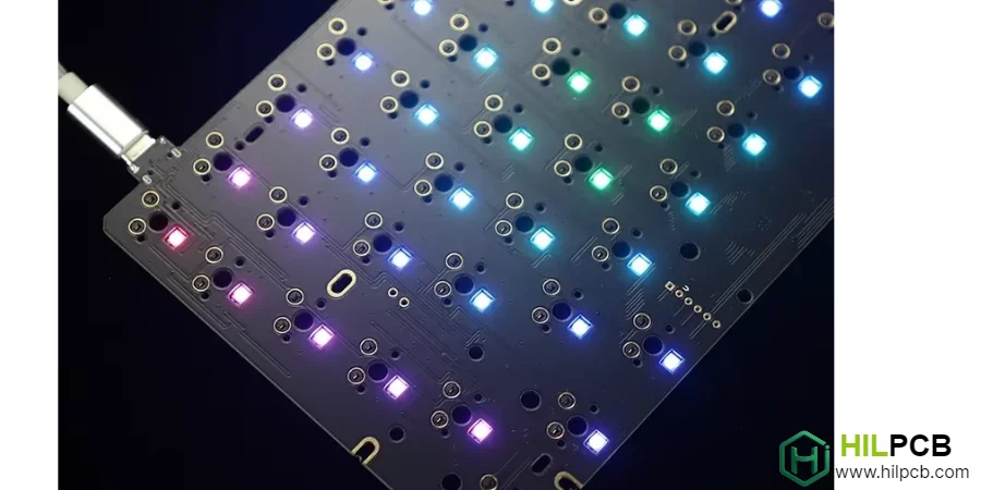
RGB lighting has evolved from gaming novelty to essential keyboard feature, with users expecting vibrant, customizable illumination across all product tiers. Implementing RGB Keyboard PCB requires careful attention to LED selection, power distribution, signal integrity, and thermal management. When done right, RGB lighting enhances both aesthetics and functionality; done poorly, it creates flickering, color inconsistency, and premature failures.
This technical guide covers the engineering considerations for creating RGB keyboard PCBs that deliver stunning visual impact with reliable long-term performance.
Menu Navigation
- WS2812B, SK6812, and LED Driver ICs: Choosing the Right Technology
- USB Power Limits and RGB Power Distribution Design
- Data Line Routing and Signal Integrity for LED Chains
- Thermal Management for High-Density LED Arrays
- QMK RGB Matrix, VIA Configuration, and Firmware Integration
WS2812B, SK6812, and LED Driver ICs: Choosing the Right Technology
Selecting the right LED technology establishes the foundation for RGB keyboard implementation. Each option offers different trade-offs in cost, capability, and design complexity.
1. Addressable RGB LEDs
Single-wire addressable LEDs dominate keyboard RGB implementations. WS2812B provides the most common addressable solution with integrated controller. SK6812 offers improved color consistency with similar interface. APA102 delivers higher refresh rates with dual-wire interface for demanding applications. These LEDs simplify routing by daisy-chaining data through each LED sequentially.
2. LED Driver IC Solutions
Dedicated LED drivers offer advantages for larger keyboards:
- IS31FL3733/3741: Matrix drivers controlling up to 144 LEDs with I²C interface.
- Independent PWM: Individual brightness control without affecting other LEDs.
- Current Regulation: Consistent brightness regardless of supply voltage variation.
- Reduced MCU Load: Offloads LED calculations from main controller.
3. Discrete LED Approaches
Traditional discrete RGB LEDs with separate driver circuits:
- Lower Component Cost: Individual LEDs less expensive than integrated solutions.
- Design Complexity: Requires more routing and driver circuitry.
- Color Mixing: RGB dies in single package require careful current matching.
- Legacy Designs: Common in older keyboard designs before addressable LED adoption.
Our Custom PCB for Keyboards services support all LED technologies with optimized implementation for each approach.
USB Power Limits and RGB Power Distribution Design
RGB LED arrays demand significant power, with full-brightness white requiring 60mA per LED. Proper power distribution ensures stable operation without voltage drop or thermal issues.
Power Budget Calculation
Understanding power requirements prevents design problems. Per-LED power consumption varies by color—red requires less than blue or green. White (all colors full) demands maximum current at approximately 60mA per LED. A 60% keyboard with 61 LEDs could draw 3.66A at full white. TKL with 87 LEDs may require over 5A peak current capacity.
Distribution Network Design
Power delivery must maintain voltage across the entire LED array:
- Multiple Power Injection Points: Feed power at multiple locations rather than single point.
- Wide Power Traces: Size traces for current density without excessive voltage drop.
- Copper Pours: Use power planes where possible for lowest impedance.
- Decoupling Capacitors: Local capacitance at LED groups prevents voltage sag during transitions.
USB Power Limitations
Standard USB ports limit available power for keyboard operation. USB 2.0 provides 500mA maximum—insufficient for full RGB at maximum brightness. USB 3.0 offers 900mA but still constrains large LED arrays. USB-C with Power Delivery can negotiate higher power levels. Firmware brightness limiting prevents overcurrent conditions during operation.
Power Regulation
Clean, stable voltage ensures consistent LED performance. Main 5V regulation from USB input powers addressable LEDs directly. LDO regulators provide clean 3.3V for MCU and sensitive circuits. Current limiting protects against fault conditions. Multi-Layer PCB for Keyboards enables dedicated power planes for lowest impedance distribution.
Data Line Routing and Signal Integrity for LED Chains
Addressable LEDs require clean data signals for reliable operation. Signal integrity issues cause flickering, incorrect colors, or complete communication failure.
1. Data Line Routing
Single-wire addressable LEDs demand careful signal routing:
- Controlled Impedance: Match trace impedance to LED requirements (typically not critical at LED data rates).
- Series Termination: 33-100Ω resistor near data source dampens reflections.
- Avoid Long Stubs: Route data line directly through LED chain without branching.
- Ground Reference: Route data adjacent to ground plane for clean return path.
2. Chain Length Considerations
Long LED chains accumulate signal degradation. Each LED reshapes data signal, but timing margins decrease through chain. Maximum practical chain length depends on LED type and data rate. Signal regeneration using multiple data outputs from MCU enables longer total counts. High-Density PCB for Keyboards routing may require careful planning for complex LED arrangements.
3. Layout Optimization
Physical LED arrangement affects routing complexity:
- Row-by-Row Routing: Snake pattern through keyboard rows minimizes total trace length.
- Matrix Arrangement: LED driver ICs enable matrix addressing reducing routing density.
- Underglow Integration: Separate data chain for edge LEDs simplifies main board routing.
- Flex Interconnects: Flexible PCB for Keyboards can route to separate underglow boards.

Thermal Management for High-Density LED Arrays
While individual LED power is modest, combined array dissipation requires thermal consideration to ensure reliability and consistent performance.
Heat Generation Sources
Understanding heat sources guides thermal design. LED junction heating during operation—efficiency around 20-30% means majority of power becomes heat. Driver IC dissipation in regulated current implementations. Trace resistance heating with high currents through narrow conductors. Localized hot spots where multiple LEDs cluster.
Thermal Design Strategies
Managing heat prevents performance degradation and early failures:
- Copper Distribution: Thermal vias and copper pours spread heat from LED pads.
- Component Spacing: Adequate spacing prevents thermal interaction between LEDs.
- Power Derating: Reduce maximum brightness to limit thermal stress.
- High-Thermal PCB Options: Aluminum-backed PCBs for extreme applications.
Reliability Implications
Temperature directly affects LED lifetime and color consistency. High junction temperature accelerates LED degradation. Color shift occurs as LEDs age at different rates based on temperature. Design margin ensures performance throughout product lifetime. Testing at elevated temperature validates thermal design adequacy.
QMK RGB Matrix, VIA Configuration, and Firmware Integration
RGB implementation extends beyond hardware to include firmware control and user configuration capability.
1. QMK RGB Matrix Support
QMK provides comprehensive RGB lighting framework:
- Per-Key Control: Individual color and brightness for each LED.
- Animation Effects: Built-in effects including reactive, rainbow, and breathing patterns.
- Layer Integration: Colors can indicate active keyboard layers.
- Hardware Abstraction: Support for multiple LED driver types.
2. VIA/VIAL Compatibility
User configuration without reflashing firmware. Real-time color adjustment through graphical interface. Effect selection and customization without programming knowledge. Profile saving enables quick switching between configurations. RGB Backlit Keyboard PCB designs benefit from VIA support for user-friendly setup.
3. Hardware Control Options
Some implementations require standalone operation without host software:
- Onboard Controls: Button or encoder for effect cycling.
- EEPROM Storage: Persistent settings without host connection.
- Standalone Modes: Full functionality without configuration software.
- Default Behaviors: Sensible out-of-box experience before customization.
Design Support
Our Mechanical Keyboard PCB services include RGB implementation expertise from schematic design through firmware integration. Whether implementing simple single-color backlighting or sophisticated per-key RGB with animations, we provide comprehensive support for your RGB Keyboard PCB project.
Common Questions
What determines the power budget of an RGB keyboard PCB?
LED count, peak brightness, animation style, USB power limits, and regulator efficiency set the real budget. The design should be sized for worst-case current instead of average demo patterns.
Why do firmware and configuration tools matter in RGB keyboard design?
QMK and VIA or VIAL determine how easily users can control effects, layers, and default behaviors. Strong firmware support reduces rework because many lighting changes can be handled without redesigning hardware.
How do you improve reliability in dense RGB keyboard layouts?
Control heat, keep data routing consistent, and provide predictable power distribution across the LED chain. Reliability improves when thermal load, chain length, and default brightness are considered early in layout.