
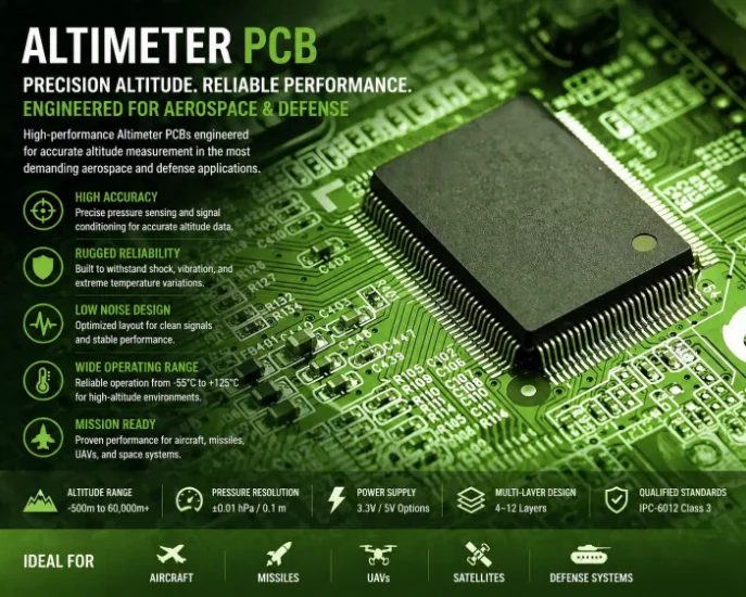
Altimeters measure altitude — the vertical distance above a reference surface. With the global drone market projected to reach $54.6 billion by 2030 and commercial avionics modernization accelerating across North America and Europe, demand for precision altimeter PCBs is growing at every accuracy tier: from ±3 meter commercial aviation boards through ±0.5 meter terrain-following military systems to ±0.1 meter precision UAV landing modules.
Three fundamentally different sensing technologies measure altitude, each with distinct PCB requirements. Barometric altimeters convert atmospheric pressure to altitude. Radar altimeters transmit microwave pulses and time the return. Laser altimeters use pulsed rangefinding for centimeter-level accuracy. HILPCB fabricates altimeter PCBs across all three technologies — from 4-layer barometric sensor boards at $8–15 per unit to 12-layer hybrid Rogers/FR-4 radar altimeter assemblies exceeding $400.
HILPCB Manufacturing Capability: We fabricate altimeter PCBs with precision analog conditioning for barometric sensors, high-frequency RF hybrid stack-ups for C-band radar altimeters, and IPC-6012 Class 3 qualification for aviation programs serving Airbus, Boeing, and military aircraft supply chains across the United States, France, Germany, and the United Kingdom.
In This Guide
- Barometric Altimeter PCB Design
- Radar Altimeter RF Electronics
- Laser Altimeter and Multi-Sensor Fusion
- Aviation Certification and DO-160 Testing
- Drone and UAV Altimeter Integration
- Why Defense and Aviation OEMs Choose HILPCB
Barometric Altimeter PCB Design
Barometric altimeters convert atmospheric pressure to altitude through the standard atmosphere model. MEMS pressure sensors from Bosch (BMP390, ±1 Pa resolution), TE Connectivity (MS5611), and Infineon (DPS310) have driven board-level cost below $10 for consumer drone modules — but aviation-grade boards achieving ±30 ft accuracy per FAR Part 91.411 require an entirely different PCB approach.The aviation barometric altimeter PCB demands:
- Redundant Sensors: Dual MEMS sensors on isolated power rails with cross-checking logic for measurement integrity — meeting DAL-A/B reliability requirements.
- 24-Bit Digitization: Noise floor below 0.5 Pa (±0.04 m altitude equivalent) with oversampling and digital averaging.
- Pressure Port Design: The sensor must be exposed to ambient pressure through a port excluding wind-induced dynamic pressure. Conformal coating must be masked within 2 mm of the port — any obstruction shifts readings beyond ±0.1 Pa tolerance.
- Temperature Compensation: Co-located precision sensor (±0.1°C) calibrated at 5 points across -40°C to +70°C, compensating the sensor's ±0.5 Pa/°C temperature coefficient.
The board is typically 4–8 layers on high-Tg FR-4 (Tg ≥170°C), with ARINC 429 or RS-422 output interfaces for aircraft bus integration. HILPCB's precision analog layouts feature dedicated ground plane architecture and multi-stage power filtering optimized for sub-pascal pressure resolution.
Radar Altimeter RF Electronics
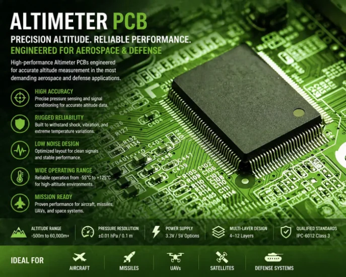
Radar altimeters represent the most RF-intensive altitude measurement category. FMCW systems transmit a continuously swept signal at 4.2–4.4 GHz (C-band) and measure the frequency difference between transmitted and received signals — proportional to altitude.The RF section requires Rogers 4350B or PTFE material for low loss at 4.3 GHz, while the baseband processing uses standard high-Tg FR-4. HILPCB's hybrid stack-up approach places RF material on the outer layers with FR-4 for the digital core — typically 8–12 layers on a multilayer construction with VNA verification coupon structures validating RF performance before boards ship.
Pulsed radar altimeters time the round-trip delay of short RF pulses (10–100 ns) with ±1 ns precision (±0.15 m altitude accuracy). The transmitter section requires heavy copper traces (2–4 oz) for pulsed RF amplifier bias networks where peak currents reach several amperes per pulse.
Both architectures must comply with DO-160G Section 21 emission limits and RTCA/DO-155. HILPCB's production VNA testing verifies transmit/receive isolation (>40 dB), antenna return loss (<-15 dB), and beat frequency gain flatness (±1 dB) on every radar altimeter board.
Laser Altimeter and Multi-Sensor Fusion
Modern altitude measurement increasingly combines technologies. Laser altimeters using pulsed rangefinding (5–20 ns pulses at 905 nm or 1550 nm eye-safe) achieve centimeter precision for precision landing and topographic survey — markets growing at 12.3% CAGR through 2030 driven by autonomous drone operations.The laser altimeter PCB requires heavy copper (2–4 oz) for 10–50 A peak pulsed current paths, high-voltage isolation (200–400 V APD bias), and matched trace lengths (±0.5 mm) for nanosecond timing. The PCB must isolate high-voltage pulsed circuits from the sensitive time-to-digital converter measurement path.
Multi-sensor altitude fusion boards integrate a MEMS barometric sensor, GPS receiver, 3-axis accelerometer, and ARM Cortex-M4 processor running a Kalman filter — combining barometric accuracy (short-term), GPS altitude (absolute), radar/laser (terrain-relative), and inertial data (high-rate estimation) into a robust all-condition altitude reference. This 4–6 layer mixed-signal board requires dedicated ground planes between analog, RF, and digital sections.
Communication interfaces to host avionics include CAN for UAV flight controllers, ARINC 429 for commercial aviation, and MIL-STD-1553B for military platforms.
Aviation Certification and DO-160 Testing
Altimeter PCBs for certified aircraft operate under one of the most rigorous regulatory frameworks in electronics. DO-160G environmental qualification covers temperature (-55°C to +70°C), altitude (up to 55,000 ft — reduced pressure affects dielectric withstand), vibration (5–2000 Hz random), and EMI/EMC (Sections 21/22). For DAL-A/B altimeters, DO-254 requires configuration management, formal verification, and manufacturing controls extending to the PCB fabricator.HILPCB's aviation program support provides the quality evidence chain that EASA and FAA certification authorities require:
- Temperature Chamber Testing: 3–5 point verification (-40°C, 0°C, +25°C, +55°C, +70°C) validating sensor-plus-electronics accuracy across the operating range.
- RF Thermal Stability: VNA verification across temperature confirming that material expansion does not shift radar altimeter impedance beyond ±5%.
- AS9102 Documentation: First Article Inspection per AS9102 with full material lot traceability, process parameter recording, and IPC-6012 Class 3 certification.
- Redundancy Validation: Independent power regulation and physically separated signal paths verified through production testing for dual-sensor architectures.
Drone and UAV Altimeter Integration
UAV altimeters face unique constraints — under 5 g weight, under 1 mW average power consumption, and production volumes reaching 10,000+ units per year. The pressure sensor must be isolated from rotor downwash through foam wind screens and pressure port routing away from propeller turbulence.HILPCB's UAV altimeter production addresses both technical and economic requirements. HDI construction on 2–4 layers with 0201 passives achieves the miniaturization that drone form factors demand. Design for automated SMT assembly — fiducial marks, standard panelization, and accessible test points — enables the production efficiency needed for 10K+ annual volumes.
Flight controller integration requires time-stamped pressure data relative to the master clock for stable altitude hold. HILPCB provides seamless scaling from prototype (5–50 boards, 5–7 day turnaround) to volume production with consistent process control — a capability that drone OEMs across the United States, China, Israel, and Europe rely on for new product introduction timelines measured in weeks, not months.
Why Defense and Aviation OEMs Choose HILPCB
HILPCB serves altimeter programs for aerospace companies across the United States, Canada, France, Germany, and the United Kingdom — covering all three altimeter technologies with process controls designed for altitude measurement applications.What sets HILPCB apart is the combination of RF fabrication expertise (hybrid Rogers/FR-4 stack-ups with VNA verification), precision analog capability (sub-pascal barometric sensor layouts), aviation documentation quality (AS9102, full material traceability), and manufacturing flexibility — from single-board prototypes for engineering characterization through 10,000+ unit UAV production runs.
For miniaturized installations, our rigid-flex construction enables conformal avionics packaging that folds into tight enclosures while maintaining signal integrity across flex transitions. Typical lead times: 5–7 days prototype, 2–3 weeks production.
Altimeter PCB FAQ
Why do radar altimeters require hybrid PCB stack-ups?
Radar altimeters use high-frequency RF signals (e.g., C-band 4.3 GHz) that require specialized low-loss materials like Rogers or PTFE for the RF layers. Using a hybrid stack-up combines these expensive RF laminates with standard FR-4 for the digital core, balancing superior high-frequency performance with cost-effective manufacturing.
What are the unique PCB requirements for barometric altimeters?
Barometric altimeter boards require extreme precision to measure sub-pascal pressure changes. This involves dual redundant sensors, 24-bit ADCs, dedicated analog ground planes for noise isolation, and careful conformal coating application that does not obstruct the sensor's pressure port.
How do UAV altimeter PCBs differ from commercial aviation altimeters?
UAV altimeters prioritize extreme miniaturization, low weight (under 5g), and low power consumption. They often utilize High Density Interconnect (HDI) construction and 0201 passives, whereas commercial aviation altimeters prioritize redundancy, DO-160G environmental qualification, and strict DAL-A/B reliability standards.