
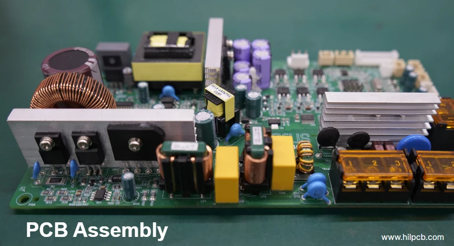
The circuit board components on a typical PCB fall into four groups: passive parts (resistors, capacitors, inductors), active parts (diodes, transistors, MOSFETs, ICs), electromechanical parts (connectors, switches, relays), and module-level parts (crystals, LEDs, fuses). Every one of these PCB components carries a silkscreen reference designator (R, C, L, Q, D, U, Y, F...) and a distinct package shape, so once you learn the designator prefixes and the common package outlines, identifying circuit board components becomes a repeatable visual process rather than guesswork. This guide explains what the main electronic components on a PCB do, how to read their markings, and how to verify them with basic instruments.
Whether you call them electronic components PCB parts, components of a circuit board, or simply PCB board components — and whatever word order you search, from components circuit board to circuit board electronic components — the vocabulary below is the same vocabulary used on schematics, bills of materials (BOMs), and assembly drawings, so learning it pays off across design, repair, and procurement work.
Common PCB Component Categories
Most printed circuit board components belong to one of four functional families. Knowing the family narrows down what an unknown part is before you even read its markings.
Passive Components
Passive parts consume or store energy but cannot amplify or switch signals on their own.
- Resistors (R): Limit current, divide voltages, pull logic lines up or down, and terminate transmission lines. The most numerous of all components on a circuit board — a dense smartphone board can carry several hundred.
- Capacitors (C): Store charge, decouple IC power pins, filter noise, and set timing with resistors. Ceramic, tantalum, aluminum electrolytic, and film dielectrics dominate.
- Inductors (L): Store energy in magnetic fields. Found in switching power supplies, EMI filters, and RF matching networks.
Active Components
Active parts control current flow using a control terminal or junction and require power to operate.
- Diodes (D): Pass current in one direction only. Subtypes include rectifier, Schottky, Zener (voltage regulation), TVS (surge protection), and light-emitting diodes.
- Transistors (Q): BJTs and MOSFETs act as switches or amplifiers. MOSFETs handle nearly all power switching in modern designs.
- Integrated Circuits (U or IC): Microcontrollers, op-amps, voltage regulators, memory, and application-specific chips — the "brains" among the electronic circuit board components, packing thousands to billions of transistors into one package.
Electromechanical Components
- Connectors (J or P): Board-to-wire, board-to-board, USB, HDMI, FPC/FFC, and pin headers that route signals and power off the board.
- Switches (SW or S): Tactile pushbuttons, DIP switches, slide and rotary switches for user input and configuration.
- Relays (K or RL): Electrically isolated mechanical switches driven by a coil, used where a low-voltage circuit must switch a high-power load.
Module-Level and Protective Components
- Crystals and oscillators (Y or X): Generate the clock references that digital ICs run on, typically 8–50 MHz for MCUs.
- LEDs (D or LED): Status indication and illumination; electrically diodes but usually grouped by function.
- Fuses and protection parts (F): Fuses, PTC resettable fuses, and varistors (MOV) that protect downstream circuitry from overcurrent and overvoltage.
Reference Designators and Circuit Board Component Identification
Every circuit board component is labeled on the silkscreen with a reference designator: one or two letters identifying the component class, followed by a serial number (R12, C104, U3). This labeling convention, standardized in IPC documentation and used by virtually every CAD tool, is the backbone of circuit board components identification — formally, printed circuit board component identification starts with the silkscreen, because the designator on the board matches the same designator on the schematic and the BOM, tying physical part, circuit function, and purchasing line item together.
| Designator Prefix | Component Type | Primary Function |
|---|---|---|
| R | Resistor | Current limiting, voltage division |
| C | Capacitor | Charge storage, decoupling, filtering |
| L | Inductor | Energy storage, EMI filtering |
| D | Diode | One-way conduction, protection, LED |
| Q | Transistor / MOSFET | Switching, amplification |
| U (or IC) | Integrated circuit | Processing, regulation, memory |
| Y (or X) | Crystal / oscillator | Clock generation |
| F | Fuse | Overcurrent protection |
| J / P | Connector | Off-board signal and power interface |
| K / RL | Relay | Isolated high-power switching |
| SW / S | Switch | User input, configuration |
| T | Transformer | Voltage conversion, isolation |
Reading Component Markings and Value Codes
Beyond the designator, the markings printed on the part itself complete PCB component identification:
- Resistor codes: SMD resistors use a 3- or 4-digit code where the last digit is the multiplier — "103" means 10 × 10³ = 10 kΩ. Precision parts use the EIA-96 two-digit-plus-letter system.
- SMD size codes: Chip parts are named by footprint, in imperial (0402, 0603, 0805, 1206 — hundredths of an inch) or metric (1005, 1608, 2012, 3216 — tenths of a millimeter). "0805" and "2012" describe the same case.
- Capacitors and ICs: Small ceramic capacitors often carry no marking at all; identification then relies on the designator and the BOM. ICs carry the manufacturer logo, part number, date code, and a pin-1 dimple or bevel.
- Polarity marks: Electrolytic capacitors show a stripe on the negative terminal; diodes show a band at the cathode; LEDs use a chamfered corner or green dot. The silkscreen repeats these marks next to the footprint.
When you need circuit board component labels explained in schematic-symbol form — the symbol each designator maps to on the drawing — our schematic symbols guide covers the drawing-side counterpart of the same identification system.
Circuit Board Components List and What Each Part Does
The circuit board components list below covers the parts you will actually encounter on most boards, organized for quick lookup. Use it as a working PCB components list when reading an unfamiliar board or cross-checking a BOM — it summarizes the circuit board components and what they do in one place.
| Component | Designator | What It Does | Typical Packages |
|---|---|---|---|
| Resistor | R | Limits current, divides voltage | 0402–2512 chip, axial through-hole |
| Ceramic capacitor | C | Decouples IC power pins, filters noise | 0402–1210 chip |
| Electrolytic capacitor | C | Bulk energy storage, smoothing | Radial can, SMD V-chip |
| Inductor | L | Filters, stores energy in DC-DC converters | Molded SMD, toroid |
| Diode | D | Rectification, reverse-polarity protection | SOD-123, SMA, DO-41 |
| Zener / TVS diode | D | Voltage clamp and surge protection | SOD-323, SMA, SMB |
| BJT transistor | Q | Low-power switching and amplification | SOT-23, TO-92 |
| MOSFET | Q | Efficient power switching | SOT-23, SOP-8, DPAK, DFN |
| Voltage regulator | U | Steps down and stabilizes supply rails | SOT-223, SOT-89, TO-252 |
| Microcontroller (MCU) | U | Runs firmware, controls the system | QFP, QFN, BGA |
| Op-amp / analog IC | U | Signal conditioning, amplification | SOIC-8, SOT-23-5 |
| Crystal / oscillator | Y | Generates clock frequency | HC-49, 3225/5032 SMD |
| LED | D / LED | Status indication, illumination | 0603–1206 chip, 3/5 mm round |
| Connector | J / P | Off-board power and signal interface | Pin headers, USB, FPC |
| Tactile switch | SW | Momentary user input | 6×6 mm SMD, through-hole |
| Fuse / PTC | F | Protects against overcurrent | 1206–2920 SMD, radial |
How to Identify Components on a Circuit Board
For repair, reverse engineering, or incoming inspection, the practical question is how to identify PCB components on a physical board in front of you. Work through these steps in order — the same sequence experienced technicians use when identifying components on a circuit board:
- Read the silkscreen designator first. The R/C/L/Q/D/U prefix tells you the component class immediately and points you to the matching schematic and BOM line. This single step resolves most of circuit board component identification.
- Match the package outline. Package shape separates lookalikes: a SOT-23 three-pin part is a transistor, diode array, or small regulator; a molded block near an inductor is usually a power IC; a shiny metal can is almost always a crystal.
- Read the part markings. Use magnification (10× loupe or microscope) to read resistor codes, IC part numbers, and polarity marks. A phone camera in macro mode works for larger parts — effectively a pocket circuit board component identifier.
- Verify with instruments. A multimeter measures resistor values in-circuit approximately, checks diode junctions on the diode range (≈0.5–0.7 V forward for silicon), and confirms fuse continuity. An LCR meter measures capacitance and inductance of removed parts for exact values.
- Look for failure signs. Bulging or leaking electrolytic capacitors, discolored or charred resistors, cracked solder joints on connectors, and heat-darkened areas around MOSFETs are the classic visual faults.
Many engineers keep a laminated reference card or circuit board components identification PDF at the bench combining designator prefixes, SMD size codes, and package outlines; the two tables above serve the same purpose and can be printed for lab use. Whether you are performing PCB components identification for a failure analysis, learning to identify circuit board components as a student, or working to identify PCB components during a repair, the designator-first method is the fastest reliable path — start from the PCB component label on the silkscreen, confirm with the package, and only then reach for instruments.
SMD vs. Through-Hole Components
The same electrical part often exists in two mounting styles, and recognizing both is part of reading modern and legacy boards:
- SMD / SMT (surface-mount): Small flat packages soldered to pads on the board surface — every chip resistor, QFP, and BGA on a modern board. Enables automated high-speed assembly and boards on both sides.
- Through-hole (THT): Leads inserted into plated holes and wave- or hand-soldered — larger electrolytic capacitors, connectors, transformers, and power parts that need mechanical strength.
A single PCB with components of both types is common: SMD for the dense logic, through-hole for connectors and bulk capacitance.
From Identified Components to Assembly
Once you can name the components on a PCB, the next practical step is usually procurement or assembly, and here the identification vocabulary turns into purchasing data. Every component PCB designers place on a schematic eventually becomes a purchasing line item: each line of a bill of materials is one circuit board component, defined by designator, manufacturer part number (MPN), value, package, and quantity. Errors at this handoff are expensive — our guide to BOM error checking for component procurement explains how to validate MPNs, lifecycle status, and aliases before release.
When the BOM is clean, the PCBA components pass to the assembly line: solder-paste printing, pick-and-place, reflow, and inspection. The components for PCB assembly you have identified on the schematic and silkscreen become the machine placement program and the inspection plan. For that stage, our PCB assembly service covers SMT and through-hole assembly from prototype to volume — submit your Gerber files, BOM, and pick-and-place (centroid) data for a DFM review and quotation.
Frequently Asked Questions (FAQ)
What is a circuit board component?
A circuit board component is any individual electronic part soldered onto a printed circuit board — resistors, capacitors, inductors, diodes, transistors, integrated circuits, connectors, switches, and protective parts. Together, the components of a PCB form the working circuit: the bare board only interconnects them.
How do you identify PCB components?
Start with the silkscreen reference designator (R = resistor, C = capacitor, U = IC), then confirm by package shape and part markings, and finally verify values with a multimeter or LCR meter. The designator matches the schematic and BOM, so how to identify circuit board components is mostly a matter of learning the prefix table.
What are reference designators?
Reference designators are the letter-plus-number labels (R12, C104, U3) printed on the silkscreen next to each part. The letter identifies the component class and the number is unique per part, linking the physical circuit board electronic components to their schematic symbols and BOM lines.
What is the difference between SMD and through-hole components?
SMD (surface-mount) parts are soldered to flat pads on the board surface and suit automated high-density assembly; through-hole parts have wire leads inserted through plated holes and offer greater mechanical strength for connectors, transformers, and large capacitors. Many boards use both.
What is a BOM?
A BOM (bill of materials) is the complete list of electronic circuit components needed to build one board: designators, manufacturer part numbers, values, packages, and quantities. It is the master document for purchasing and for programming the pick-and-place machines during assembly.
What are the most common components on a PCB?
Resistors are by far the most numerous, followed by ceramic capacitors — together they can account for over half of all components of PCB assemblies. After those come ICs, diodes, transistors, inductors, connectors, crystals, LEDs, and fuses.
Partner with HILPCB for Component Sourcing and PCB Assembly
HILPCB provides end-to-end support from component sourcing to finished assembly:
- Full turnkey and consigned assembly: We procure all circuitry components against your BOM with traceable supply chains, or assemble from your consigned kits.
- SMT and through-hole under one roof: Fine-pitch SMD placement down to 01005 and BGA, plus wave and selective soldering for through-hole parts.
- Inspection at every stage: Solder paste inspection (SPI), AOI, and 3D X-ray (AXI) for hidden joints, with first-article verification before volume runs.
Upload your Gerber files, BOM, and pick-and-place data to the HILPCB PCB assembly team for a free DFM analysis and a competitive quotation — from a PCB with components in prototype quantities to full production volumes.
Selecting footprint packages with standard pad geometries ensures seamless compatibility with automated pcb board fabrication and high-speed pick-and-place lines.
Verifying pinout orientations and solderability during early rapid pcb prototyping cycles prevents component package footprint errors.