
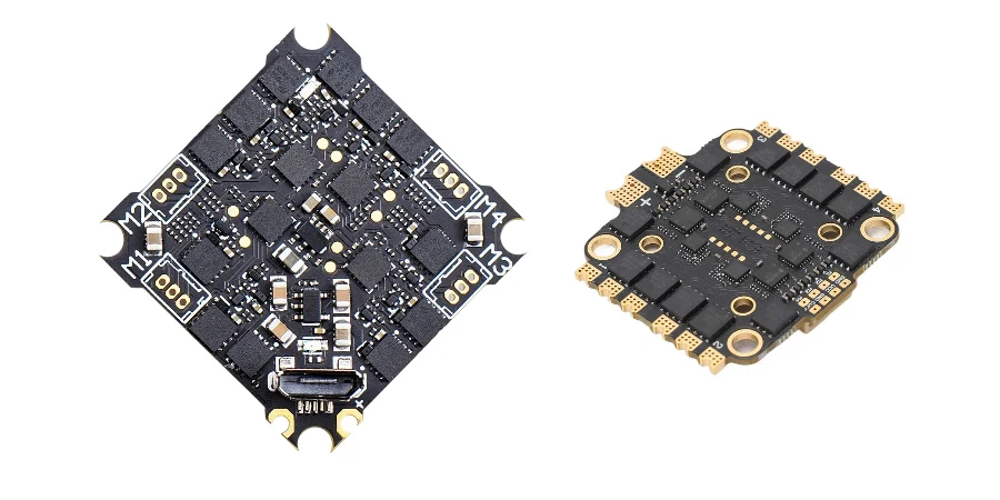
A UAV condition monitoring PCB acquires time-correlated health data from power, propulsion, flight-control, structural and payload subsystems so software or operators can detect abnormal behavior and make a defined maintenance or flight decision. It is not automatically a safety controller, a battery-management system or a predictive-maintenance guarantee.
Key Takeaways
- Start with failure hypotheses and decisions, then select sensors; more data does not prove useful coverage.
- Keep fast protection in the ESC, BMS, power stage or flight controller as required. Monitoring and cloud analytics must not become the only barrier to an unsafe condition.
- Treat battery state of charge and state of health as estimates whose accuracy depends on calibration, chemistry, temperature, load and history.
- ESC telemetry may report RPM, current, voltage, temperature and error events, but fields and update rates depend on the device and protocol.
- Vibration features need controlled mounting, sampling, rotor-speed context and baselines; one peak does not identify bearing wear.
- Correlate each health indicator to an action, false-alarm policy, fallback and verification test.
- Partition motor-current returns, switching nodes, RF, GNSS and sensor references before adding shields or split grounds.
- Qualify the aircraft and algorithms for the mission; PCB inspection cannot establish airworthiness.
Table of Contents
- Define Monitoring, Protection and Flight Decisions
- Build a Sensor-to-Action Coverage Matrix
- Design the Data Acquisition Chain
- Monitor Battery and Power Without Overclaiming SoH
- Monitor ESC, Motor and Propulsion Health
- Use Vibration Data Without Misdiagnosing the UAV
- Monitor Navigation, Links and Mission Payloads
- Choose Onboard, Ground and Fleet Analytics Boundaries
- Control PCB Noise, Power Integrity and Layout
- Design Fault Logic, Data Quality and Recovery
- Translate Mission Risk into PCB Manufacturing Evidence
- Validate with Fault Injection and Environmental Tests
- Diagnose Common UAV Monitoring Failures
- UAV Condition Monitoring PCB RFQ Checklist
- Reference Standards and Responsibility Boundaries
- How HILPCB Supports UAV Monitoring PCB Programs
- FAQ
- Conclusion
Define Monitoring, Protection and Flight Decisions
Condition monitoring observes trends and anomalies. Protection reacts within a bounded time to an unsafe electrical or thermal condition. Flight management decides whether to continue, derate, return, land or abort. Maintenance analytics decides whether a component needs inspection or replacement.
These functions can share data but not assumptions. Slow telemetry may support maintenance while a local circuit protects the power stage. Fleet analytics should not command an emergency maneuver unless the complete safety path is validated.
Define four states for every critical channel:
- valid data and normal subsystem;
- valid data and detected anomaly;
- missing, stale, saturated or implausible data;
- monitor/controller reset or communication loss.
“No alarm” is not evidence of health when the monitor may have failed.
Build a Sensor-to-Action Coverage Matrix
The matrix below prevents a temperature, vibration or current channel from being added without a decision purpose.
| Failure hypothesis | Observables | Confounders to control | Permitted decision | Verification evidence |
|---|---|---|---|---|
| Battery energy is lower than expected | Pack/cell voltage, current, temperature, consumed charge | Chemistry, load sag, capacity setting, sensor calibration | Warn, restrict mission or return using validated thresholds | Calibrated discharge profiles and low-energy flight scenarios |
| Battery connection or power path is degrading | Voltage drop under load, connector/shunt temperature, current | Ambient and workload variation | Maintenance flag; land if limits are exceeded | Four-wire resistance and thermal/load testing |
| One motor/ESC channel is abnormal | RPM, commanded duty, phase/DC current, ESC temperature, error flags | Wind, maneuver, propeller differences, payload | Cross-check, derate or flight action per hazard analysis | Prop damage, motor/ESC fault and asymmetric-load injection |
| Propeller imbalance or structural looseness | IMU/accelerometer spectrum, RPM/order features | Airframe modes, sensor mount, maneuver and aliasing | Maintenance inspection; flight action only with validated severity | Baseline fleet data and controlled imbalance tests |
| Flight-controller sensor is drifting | Redundant IMU/barometer/GNSS residuals, temperature | Vehicle dynamics and environmental changes | Reject/degrade sensor or change estimator mode | Bias, stuck-value, ramp and temperature tests |
| Cooling or payload load is abnormal | Local temperature, current, fan/pump state where fitted | Solar load, ambient, airflow and duty cycle | Reduce payload duty, return or maintenance flag | Thermal chamber and blocked-airflow/load tests |
| Data link is degraded | RSSI/SNR, packet loss, latency, error counters | Range, antenna orientation and interference | Execute the approved link-loss behavior | Attenuation, interference and link-drop tests |
This is a coverage claim, not a proof of fault isolation. Similar symptoms can have different causes, so the design should expose uncertainty rather than label every anomaly as a specific failure.
Design the Data Acquisition Chain
A credible channel needs more than a sensor part number. Specify:
- measurement range, overload survival, accuracy and temperature drift;
- bandwidth, sample rate, anti-alias filter and timestamp accuracy;
- placement, orientation, mounting and cable/trace loading;
- ADC reference, input protection, common-mode range and saturation behavior;
- calibration, stored coefficients, revision and recalibration trigger;
- data-valid, stale, clipped, out-of-range and self-test status;
- processing latency, buffer capacity and lost-sample indication.
For motor command, RPM, current and vibration correlation, define clock synchronization, jitter and maximum skew. Asynchronous data can implicate the wrong propulsion channel.
ISO 13374-1 provides a general framework for machine-condition data processing, communication and presentation, while ISO 17359 covers principles for setting up a condition-monitoring program. They are useful architecture references, not UAV airworthiness approvals.
Monitor Battery and Power Without Overclaiming SoH
Voltage is not remaining capacity. Terminal voltage changes with chemistry, state of charge, current, temperature, cell variation and aging. Current integration also needs an initial state and accumulates sensor error.
PX4 documentation illustrates this distinction: it can combine voltage-based estimates, load compensation and integrated current, and it requires calibration of voltage and current measurement. The result is still an estimate used for warnings and failsafe logic.
For a smart battery or BMS interface, define:
- pack and cell measurements actually available;
- current-sensor range, offset, drift and bidirectional behavior;
- temperature sensor locations and thermal lag;
- capacity, cycle, imbalance and resistance-estimation methods;
- message age, CRC/status, disconnect and reset behavior;
- ownership of overcharge, over-discharge, short-circuit and thermal protection.
Do not promise precise SoH from one flight. Capacity and resistance trends need comparable conditions. Thermal-runaway prevention depends on cells, pack, charging, protection and system response—not one PCB.
Monitor ESC, Motor and Propulsion Health
Depending on the ESC and interface, telemetry may provide RPM, voltage, current, temperature, consumed charge and error events. ArduPilot documents these fields for supported ESC telemetry, but also notes protocol and device differences. Verify the exact ESC firmware, pole-count conversion, update rate and aggregation behavior.
Useful propulsion residuals include:
- commanded versus measured RPM;
- RPM-normalized current or power;
- temperature rise versus load and airflow;
- channel-to-channel imbalance under comparable commands;
- commutation, desynchronization, stall or reset flags;
- vibration energy at rotor order and harmonics.
Residuals can outperform one threshold, but maneuver, wind, propeller and payload affect them. Baseline each configuration and operating region. The ESC retains required local protections.
Use Vibration Data Without Misdiagnosing the UAV
UAV accelerometers measure airframe dynamics as well as faults. Sensor location, damping, structural modes, motor speed, maneuver and aliasing all shape the signal. Excessive vibration can also corrupt navigation estimates before it becomes a useful maintenance indicator.
ArduPilot exposes vibration and accelerometer-clipping data and supports FFT-based analysis. RPM telemetry can support harmonic notch filtering, but filtering for estimator performance and diagnosing mechanical health are different tasks.
Plan vibration monitoring around:
- usable sensor bandwidth and anti-aliasing relative to rotor speed;
- a mounting transfer function that remains stable across builds;
- raw-data or feature logging sufficient for diagnosis;
- RPM/order tracking so speed changes do not appear as new faults;
- baselines by frame, propeller, payload and flight regime;
- controlled seeded-fault tests such as known imbalance or looseness.
Never infer “bearing wear” from one peak without corroborating temperature, current, RPM behavior, inspection or teardown evidence.
Monitor Navigation, Links and Mission Payloads
Navigation monitoring can compare redundant sensors and estimator residuals. Distinguish invalid, inconsistent and physically impossible data; baseline temperature compensation and orientation.
For links, log signal quality, packet loss, latency, reconnects and protocol errors with the flight phase. RSSI alone does not describe an end-to-end control or payload link.
Payload channels follow mission and safety effects: current, temperature, storage, gimbal state, timestamp continuity and interface errors. Do not change attitude for cooling unless flight and thermal behavior are jointly validated.
Choose Onboard, Ground and Fleet Analytics Boundaries
| Processing location | Best suited to | Main constraint |
|---|---|---|
| Local hardware/ESC/BMS | Fast protection and hardware limits | Must remain deterministic and independently verified |
| Flight controller/monitor node | Cross-channel checks and bounded flight decisions | CPU, memory, bus bandwidth, timing and common-cause failure |
| Ground station | Operator alerts and mission-context review | Link availability and human response time |
| Post-flight/fleet platform | Trend analysis, model training and maintenance planning | Data quality, configuration control and model drift |
MAVLink, DroneCAN or Cyphal can transport health data, but a protocol name does not prove safety. Define message source, units, rate, timeout, priority, redundancy, authentication where required and behavior under bus saturation. Cyphal supports real-time distributed computing and redundancy concepts; the integrated network still needs timing and fault validation.
Control PCB Noise, Power Integrity and Layout
Motor and ESC currents, switch nodes, radios, GNSS receivers and MEMS sensors share a small platform. Partition by return-current path rather than applying a blanket “star ground” rule.
- Keep battery, ESC and regulator commutation loops compact and away from IMU, ADC reference and RF input regions.
- Preserve continuous reference planes for digital interfaces; do not split a plane under a high-speed return path.
- Route current shunts and bridge sensors with Kelvin connections and protect ADC inputs against transients.
- Give the IMU a quiet local supply/reference and stable mechanical mount; avoid flexible board regions and mounting-hole strain.
- Place GNSS/RF antennas and front ends using an approved keepout and impedance-controlled launch where required.
- Check brownout margin at low battery voltage with radio, payload and actuator load active.
- Define connector retention, strain relief, conformal-coating keepouts and accessible programming/test points.
Use HDI PCB when package escape or area requires it, not simply because the vehicle is small. Rigid-flex PCB can reduce cable/connectors in a qualified mechanical design, but bend radius, stiffeners, copper transitions and assembly handling must be released.
Design Fault Logic, Data Quality and Recovery
Gate every algorithm on range, change rate, timestamp, saturation, clipping, CRC, sequence and cross-sensor plausibility.
Define hysteresis, persistence and reset. Use different logic for immediate protection, flight advisory and maintenance trends.
Record airframe, propeller, battery, ESC/motor, calibration, firmware/model, payload and sampling settings. Otherwise a configuration change can look like degradation.
If an ML model is used, control training data, class imbalance, out-of-distribution behavior, false-negative/false-positive limits and rollback. A probability score is not a validated remaining-useful-life prediction unless the degradation path and uncertainty have been demonstrated for the target fleet.
Translate Mission Risk into PCB Manufacturing Evidence
| Board risk | Released control | Production evidence | Change trigger |
|---|---|---|---|
| IMU/reference noise | Stackup, placement, return path and regulator constraints | AOI plus powered sensor-noise/readout test | IMU, regulator, stackup or placement |
| ESC/power current | Copper, via, shunt, connector and thermal limits | Microsection/resistance plus load/thermal test when specified | Copper, MOSFET, connector or current limit |
| BGA/QFN/LGA sensor assembly | Pad, paste, reflow and inspection criteria | SPI/AOI and X-ray where the joint is hidden | Package, stencil, paste or profile |
| RF/GNSS interface | Material, impedance, launch and antenna keepout | Coupon/TDR or RF/link test when limits/fixture exist | Stackup, antenna, connector or enclosure |
| Flex/connector mechanics | Bend zone, stiffener, retention and strain limits | Dimensional/visual plus continuity/function test | Flex construction, connector or housing |
| Configuration | Programming image, calibration and serial trace | Checksum, calibration and functional record | Firmware, model or sensor lot |
AOI, X-ray and electrical test do not prove sensor accuracy or flight safety. Tie inspection and functional tests to the risk of each board. HILPCB can fabricate and assemble to a released specification; the OEM owns airframe integration and final flight qualification.
Validate with Fault Injection and Environmental Tests
Qualification covers operating corners, seeded faults and monitor faults:
- low/high battery voltage, load steps, brownout and power-source transfer;
- sensor open/short, stuck value, drift, saturation, clipping and wrong calibration;
- dropped, delayed, duplicated and corrupted messages; bus saturation and node reset;
- ESC/motor/propeller asymmetry, known imbalance and blocked or degraded cooling;
- temperature, vibration, shock, humidity/condensation and altitude profiles defined by the mission;
- logging overflow, storage failure, clock offset and firmware/model rollback;
- false-alarm and missed-detection measurement on representative flights.
RTCA DO-160 environmental categories and DO-254 hardware design assurance may be relevant when invoked by an aircraft certification basis. FAA AC 20-152A explains DO-254 applicability to airborne electronic hardware used for type certification or authorization; DO-254 is not a blanket manufacturing certificate for every commercial UAV PCB.
Diagnose Common UAV Monitoring Failures
| Symptom | Likely cause | Evidence | Corrective direction |
|---|---|---|---|
| Battery estimate drops suddenly | Load sag, wrong capacity, current offset or poor calibration | Calibrated voltage/current and load profile | Correct model/calibration and failsafe validation |
| One motor appears unhealthy in turns | Maneuver load or wind confounds channel comparison | Command, attitude, RPM and current correlation | Compare within equivalent operating regions |
| Vibration alarm moves between builds | Sensor mount or structural transfer changed | Mounting, raw data and RPM/order comparison | Control mechanics and re-baseline |
| Telemetry is clean during a real fault | Update/averaging too slow or data frozen | Timestamp, sequence and local protection capture | Add freshness checks and independent protection |
| GNSS/IMU degrades at throttle | ESC/regulator noise or return-current coupling | Near-field scan, rail capture and sensor residuals | Rework loops, filtering, references and placement |
| Fleet model flags a new revision | Configuration change, not degradation | Hardware/firmware/calibration history | Version models and compare like configurations |
UAV Condition Monitoring PCB RFQ Checklist
Mission/system: aircraft type, operating duration, altitude, temperature, humidity, vibration/shock, payload, propulsion architecture, critical failure hypotheses and required flight/maintenance decisions.
Sensors/data: channels, ranges, accuracy, bandwidth, sampling, timestamps, calibration, interfaces, message definitions, storage/logging and data-quality flags.
PCB/mechanics: schematic, BOM, ODB++/Gerber, stackup, impedance, copper/current limits, flex construction, outline, mass/thickness target, connectors, enclosure, antenna keepouts and coating.
Protection/firmware: local protection ownership, thresholds, monitor timeout, reset/recovery, configuration/checksum, programming and traceability.
Assembly/test: workmanship class, stencil/reflow, hidden-joint inspection, cleanliness, ICT/flying probe, sensor readout/calibration, current/thermal load, RF/link and environmental/fault-injection requirements.
For an assembled build, include fixtures, golden units, acceptance limits and firmware with the turnkey PCB assembly RFQ.
Reference Standards and Responsibility Boundaries
- ISO 13374-1 — International Organization for Standardization
- ISO 17359 — International Organization for Standardization
- RTCA DO-160 — RTCA
- RTCA DO-254 / EUROCAE ED-80 — RTCA / EUROCAE
- FAA AC 20-152A — Federal Aviation Administration
- IPC-2221 — IPC
- IPC-6012 — IPC
- IPC-A-610 — IPC
- IEC 60068-2-6 — International Electrotechnical Commission
- IEC 60068-2-27 — International Electrotechnical Commission
The applicable editions, categories, assurance levels and acceptance criteria come from the product and certification plan. PCB/PCBA production can provide material, construction, workmanship, calibration/programming and specified test evidence. It cannot alone establish airworthiness, battery safety, diagnostic accuracy, remaining useful life or safe autonomous flight behavior.
How HILPCB Supports UAV Monitoring PCB Programs
HILPCB can review a released UAV monitoring design for stackup and copper feasibility, sensor/package assembly risk, hidden-joint inspection, flex/connector construction, test access, programming and traceability. The useful deliverable is an evidence plan tied to the board's critical characteristics, not a generic claim that every drone PCB meets an aerospace standard.
Share the mission profile, sensor and power interfaces, mechanical constraints, CTQs, functional-test procedure and change-control requirements so prototype evidence can carry forward into production.
FAQ
What should a UAV condition monitoring PCB measure?
Measure only parameters connected to a failure hypothesis and decision. Common inputs include battery voltage/current/temperature, ESC RPM/current/temperature, vibration, power-rail health, sensor residuals, link quality and payload status. Required channels depend on the aircraft hazard and maintenance analysis.
Can ESC telemetry replace hardware protection?
No. ESC telemetry can support logging, diagnostics and cross-channel checks, but it can be delayed, unsupported or lost. Local overcurrent, undervoltage, overtemperature and other required protections must retain defined behavior without telemetry.
Does vibration monitoring predict motor or bearing failure?
It can detect changes associated with imbalance, looseness or mechanical degradation, but diagnosis requires RPM/order context, controlled baselines and corroborating evidence. One vibration peak cannot identify a specific fault or remaining life reliably.
Does a drone PCB need DO-254 compliance?
Only when the applicable aircraft certification basis and hardware assurance plan invoke it. DO-254 addresses design assurance for airborne electronic hardware; it is not a universal PCB fabrication or assembly standard for every consumer or industrial UAV.
Conclusion
A useful UAV condition monitoring PCB preserves measurement quality, detects monitor failures and connects each health indicator to a bounded, verified action.
Build the program around failure coverage, data quality, independent protection, configuration control and fault injection. Send HILPCB the complete electrical, mechanical, firmware and test baseline when requesting a manufacturing review or quote.