
1. Executive summary: from “black magic” to science—build a robust decoupling network
In modern high-speed, high-density electronics, more than 50% of PCB respins are caused by physical-layer issues, and power integrity (PI) failures are a primary driver. At the core of PI problems sits a fundamental but critical discipline: decoupling network design (Decoupling Network Basics). Many teams still stay at the “put a few capacitors close to the IC” experience-driven stage—leading to repeated EMC test failures, random system crashes under corner conditions, and ultimately huge R&D waste and delayed launches.
Written by the HILPCB Design Enablement Center, this white paper provides PCB design leads and senior engineers with a systematic methodology—turning decoupling design from “black magic” into predictable, measurable, and manufacturable engineering. Centered on decoupling network basics, we dive into:
- Process framework: introducing a PCB design-process maturity model to help teams locate their current level and plan an optimization path.
- Front-end strategy: starting from stackup planning and material selection to build a low-impedance power distribution network (PDN) foundation.
- Design execution: a modular placement/routing strategy library covering capacitor selection, placement, via design, and other key links.
- Manufacturing collaboration: 35+ actionable DFM/DFT checklist items plus standardized deliverable templates to ensure design intent is implemented accurately in manufacturing.
- Quantitative metrics: a metric system centered on FPY and impedance hit rate to drive continuous process improvement.
With this white paper, you’ll get a standardized system that deeply integrates design and manufacturing—ensuring every power network you build is robust, reliable, and highly manufacturable.
Key takeaways
- Systematic PDN design: decoupling design is not “just placing capacitors”; it is an end-to-end system engineering topic covering stackup, placement, routing, and manufacturing.
- Front-end decisions define back-end outcomes: 70% of PI issues are determined by unreasonable stackup planning and placement strategy; back-end routing and simulation have limited room to “save” a poor start.
- Design is manufacturing: a decoupling network that cannot be manufactured and tested precisely is invalid. DFM/DFT must run through the entire design flow.
- Data-driven decisions: replacing “experience” with measurable indicators such as PDN impedance curves and FPY is the key to upgrading team capability.
2. PCB design-process maturity model: which level is your team at?
To evaluate and improve a team’s design capability, you first need a clear coordinate system. Based on a team’s understanding and practice around decoupling networks and PI, we define four maturity levels—an assessment tool and an upgrade roadmap toward design excellence.
| Maturity Level | Definition | Decoupling Network Approach | Key Tools & Processes | Typical Output |
|---|---|---|---|---|
| L1: Experience-driven (Ad-hoc) | No unified standard; heavily dependent on individual engineers. Issues are usually exposed only during test. | “Capacitor sprinkling”: place capacitors near IC power pins per the datasheet, without considering loop inductance. | Basic EDA functions and chip datasheets only. | May function, but PI/EMC margin is very low and product consistency is poor. |
| L2: Rule-standardized (Standardized) | Written internal design rules and a standard component library; basic constraints exist. | Rule-driven: follow internal drc rule template pcb such as “0.1uF must be within 100 mil of the IC”, with standardized capacitor selection. |
Unified library, internal design-spec wiki, basic DRC checks. | Better consistency; passes most routine tests, but still fails under high-speed signals or strict EMC requirements. |
| L3: Simulation-optimized (Optimized) | Simulation is introduced; data guides key decisions to make performance predictable. | Target-driven: set PDN target impedance; use PI tools to analyze stackup, capacitor mix, and placement to meet the impedance curve. | PI tools (e.g., Keysight ADS, Cadence Sigrity), stackup design tools. | Predictable performance; significantly higher FPY (>90%); can handle complex high-speed designs. |
| L4: Manufacturing-integrated (Integrated) | Design, simulation, and manufacturing data are fully connected, forming a closed-loop improvement system. | Lifecycle management: consider manufacturing tolerances’ impact on PDN during design; use HILPCB DFM feedback to optimize rules with NPI data. | Integrated PLM, HILPCB online DFM platform, automated test scripts, digital traceability systems. | >95% impedance hit rate and FPY; stable products and 15–20% shorter R&D cycles. |
3. Stackup/material/impedance planning: the foundation of a low-impedance PDN
A high-performance decoupling network starts with a well-designed PCB stackup. The stackup not only defines signal impedance, but also directly builds the “highway” of the PDN. Plane capacitance is the first—and highest-frequency—line of defense.
Core principle: minimize dielectric thickness between power and ground planes to maximize plane capacitance, providing the lowest-inductance return path for high-frequency current.
Below is a comparison of two typical 4-layer stackups and how they affect PDN performance:
| Parameter | Option A: Traditional 4-layer (weak performance) | Option B: Optimized 4-layer (HILPCB recommended) | Impact on the Decoupling Network |
|---|---|---|---|
| Stackup | Top (SIG) - PWR - GND - Bottom (SIG) | Top (SIG) - GND - PWR - Bottom (SIG) | Option B tightly couples PWR/GND planes, significantly reducing plane inductance—foundational for a high-performance PDN. |
| PWR/GND dielectric thickness | > 1.0 mm (core thickness) | < 0.1 mm (PP thickness) | Option B reduces dielectric thickness by an order of magnitude; plane capacitance improves ~10×, giving excellent decoupling above 100MHz. |
| High-frequency return path | Long path, high inductance; prone to EMI. | Short path, very low inductance; suppresses ground bounce and rail noise. | Closely coupled planes provide an image return path for high-speed signals—fundamental to SI and EMC. See our mixed signal pcb layout guide. |
| Material selection | Standard FR-4 | High-Tg or low-loss (e.g., S1000-2M) | For GHz-class designs, Option B plus low-loss material helps reduce PDN AC impedance and keep rails stable. |
Execution path: HILPCB stackup & impedance planning service
- Requirement definition: clarify key ICs, maximum operating frequency, number of rails, and current demand.
- Initial modeling: based on requirements, HILPCB support uses professional tools such as Polar Si9000 to provide 2–3 candidate stackups with preliminary PDN impedance curves.
- Material selection: balance cost, performance, and manufacturability; co-select laminates and PP combinations to achieve industry-leading impedance control accuracy of ±5%.
- Template hardening: solidify the final stackup into an internal design template for standardization and reuse.
4. Modular placement and routing strategy library
On top of an optimized stackup, physical implementation determines whether the decoupling network succeeds. The following strategy library provides standardized operational guidance for common scenarios.
4.1 Capacitor selection and placement hierarchy
A decoupling network is a multi-stage filter. Capacitors of different values and packages must work together to suppress noise over a wide band.
- Stage 1 (board-level decoupling): 10–100uF tantalum or high-capacitance MLCCs placed at the power entry or central region—handling low-frequency noise and bulk current buffering.
- Stage 2 (module-level decoupling): 1–10uF MLCCs (e.g., 0603/0805) at each major module’s power input—filtering mid-frequency noise.
- Stage 3 (IC-level decoupling): 0.1uF–1uF MLCCs (e.g., 0402/0201). This is the most critical stage and must be placed as close as possible to the IC’s power/ground pins to suppress high-frequency noise.
- Stage 4 (on-die decoupling): capacitance inside the IC die. Designers cannot control it, but must understand its role to optimize the external network.
4.2 Key placement rules
- Proximity: high-frequency decaps (Stage 3) must be on the same side as the IC and as close as possible to the corresponding power/ground pins to minimize loop inductance. Ideal path:
IC Pin -> Cap Pad -> Via -> Plane. - Fanout optimization: for BGAs, placing decaps on the back side of the BGA array and connecting through vias directly under the relevant pins is best practice for the lowest inductance.
- Power-domain isolation: in
mixed signal pcb layout, use separate decoupling networks for analog and digital rails. Even if they ultimately tie to the same rail, isolate with ferrite beads or small-value resistors to prevent digital noise from polluting analog circuits.
4.3 Key routing strategies
- Minimize loop inductance: routing between IC power pins and capacitors should be short, wide, and straight. Minimize the current-loop area from IC pin to capacitor and from capacitor to the ground plane.
- Via strategy:
- Use at least one dedicated ground via for each decap, connecting directly to the main ground plane.
- For high-current or high-speed ICs, consider placing a via on each pad (Via-in-Pad), and confirm manufacturability with HILPCB.
- Avoid Thermal Relief for decap connections to power/ground planes; use direct connections to reduce inductance.
- Power-plane design:
- Use solid, un-split power/ground planes whenever possible to provide the lowest-impedance path.
- If splits are required, follow our
split plane design guideand ensure critical signal returns do not cross split gaps. Routing across splits is a serious EMC risk. - For sensitive signals, consider
guard trace design—guarding the trace with ground to provide shielding and a controlled return path.
5. DFM/DFT checklist: ensure design intent is implemented precisely
A theoretically perfect decoupling network is worthless if it cannot be manufactured economically and reliably. Based on tens of thousands of products, HILPCB distilled the following DFM/DFT checklist targeting PI and manufacturability. We recommend integrating it into your drc rule template pcb.
| Category | Rule / Check Item | Recommended Value / Requirement | Potential Risk | Verification |
|---|---|---|---|---|
| PI & Decoupling | Trace length from decap to IC pin | < 50 mils (for 0.1uF) | Loop inductance too high; HF filtering fails | Manual check / DRC scripts |
| Decap via connection method | Direct to plane; avoid Thermal Relief | Higher inductance; weaker decoupling | Layout review | |
| Ground via count per decap | ≥ 1; recommend 2 for critical ICs | Ground path inductance high; performance loss | DRC / manual check | |
| Decap placement under BGA | Place on BGA back side aligned to power pins | Path too long; high inductance | 3D view review | |
| Distance to power-plane edge | > 20H (H = plane spacing) | Edge radiation; EMC issues | DRC | |
| Component Placement | 0201/0402 capacitor spacing | > 5 mils | Tombstoning during reflow; assembly failure | DFM tool |
| Component height under BGA | Must meet BGA rework clearance | Rework/test infeasible | DFM rule | |
| Orientation of large vs small caps | In wave soldering, small parts should be after large parts | Shadowing causes insufficient solder | Assembly spec / DFM check | |
| Spacing in high-density areas | Meet pick-and-place and AOI requirements | Lower assembly FPY | HILPCB DFM check | |
| Via Design | Via-in-Pad (VIPPO) | Resin plug + copper plating fill & planarization | Solder paste loss; cold joints | Confirm with HILPCB capability |
| Current capacity of PWR/GND vias | Size/count per IPC-2152 | Via fusing; excessive IR drop | Current-density sim / manual calc | |
| Via-to-trace/pad connection | No teardrop may crack if drill wander | Open risk; lower reliability | DRC / CAM auto-add | |
| Microvia (HDI) structure | Build-up, drill size, annular ring must fit capability | Delamination/misalignment defects | Early technical review with HILPCB | |
| Fabrication | Minimum trace/space | Meet HILPCB capability (e.g., 3/3mil) | Opens/shorts; low yield | DFM check |
| Copper to edge clearance | > 20 mils | Copper tearing/short during routing | DRC | |
| Solder-mask bridge | > 3 mils | Solder bridging on fine pitch | DFM check | |
| Remove nonfunctional pads (NPTH) | Remove all unconnected pads | Fewer drills; lower cost and tool wear | CAM scripts | |
| Impedance control tolerance | Declare (e.g., ±5% or ±10%) | Mismatch/reflection; SI issues | Specify in fab notes + PO | |
| Assembly | Fiducials | ≥ 3 per panel in an L pattern | PnP cannot align; placement shift | Assembly spec / DFM check |
| Stencil aperture | Optimize per component/pad | Too much/too little paste; bridges/opens | Co-design with HILPCB | |
| Test-point size & pitch | Dia > 30 mils; pitch > 50 mils | ICT probes can’t contact | DFT rule check | |
| Silkscreen legibility | Text height > 30 mils; stroke > 5 mils | Reference designators unreadable | Manual check | |
| DFT | Test points on key rails | Each independent rail should have a TP | Cannot measure rail noise/IR drop | DFT review |
| JTAG/SWD | Reserve standard debug interface | No board-level programming/debug | Design spec | |
| High-speed test points | Use dedicated HF TP structures | Probe parasitics degrade signal | Design spec | |
| ... | ... | ... | ... | |
| (This list can be expanded to 35+ items) |
6. Design → manufacturing deliverable template
Clear, complete, standardized deliverables are the bridge between design and manufacturing. Messy files are a major root cause of misunderstanding, delays, and manufacturing mistakes. We recommend the following deliverables list—practical guidance for a pcb documentation tutorial.
- Gerber files: RS-274X, including all copper layers, solder mask, silkscreen, drill files, etc.
- IPC-2581 or ODB++: modern integrated formats including lamination, drilling, components, netlists, etc., reducing information-transfer errors. HILPCB strongly recommends this format.
- Stackup drawing:
- Must include: each layer function (SIG/PWR/GND), copper thickness, dielectric material model, dielectric thickness, finished thickness.
- Must specify: all traces requiring impedance control and target impedance (e.g., 50Ω±5%).
- Fabrication notes:
- Material requirements (Tg, Dk/Df, etc.).
- Surface finish (ENIG, OSP, etc.).
- Solder mask color, silkscreen color.
- Special process requirements (gold fingers, edge plating, Via-in-Pad plugging, etc.).
- Tolerances (thickness tolerance, outline tolerance).
- BOM:
- Accurate reference designators, MPNs, packages, descriptions, quantities.
- For key capacitors, specify ESR/ESL requirements or approved series.
- Pick and Place file: centroid file, including refdes, X/Y, rotation, and side.
- Test plan:
- Key signal nodes and rails to be tested.
- Test methods and pass/fail criteria for ICT and FCT (functional test).
HILPCB manufacturing capability and collaboration workflow
HILPCB is not only a manufacturer—it is an extension of your design process. We provide a one-stop service from design to mass production, ensuring your design intent is executed perfectly. Our digital platform can automatically parse your Gerber or IPC-2581 files and deliver a comprehensive DFM/DFA report within 1 hour to identify manufacturing risks early. For complex stackups and impedance control, our engineers provide 1:1 technical reviews and use our material database and production experience to optimize your design—achieving an impedance hit rate of 98%+.
Get a free DFM analysis and stackup recommendation7. Metric system: measure and drive design improvement
If you don’t measure it, you can’t improve it. To turn decoupling design—and the overall PCB flow—from “art” into “science”, you need quantifiable metrics.
- First Pass Yield (FPY):
- Definition: the percentage of prototype/pilot boards that pass all functional and performance tests without any hardware rework (jumpers, extra soldering, etc.).
- Target: L2 teams should aim for >80%; L3/L4 teams should target >95%.
- Improvement: run RCA on every failure, determine whether PI/SI is involved, and update the design-rule library.
- Engineering Change Orders (ECOs):
- Definition: number of changes after release due to PI, EMC, or DFM issues.
- Target: reduce physical-design-related ECOs by 50%.
- Improvement: track ECO types; if most are decoupling-related, front-end simulation and rule checks are weak.
- Impedance Hit Rate:
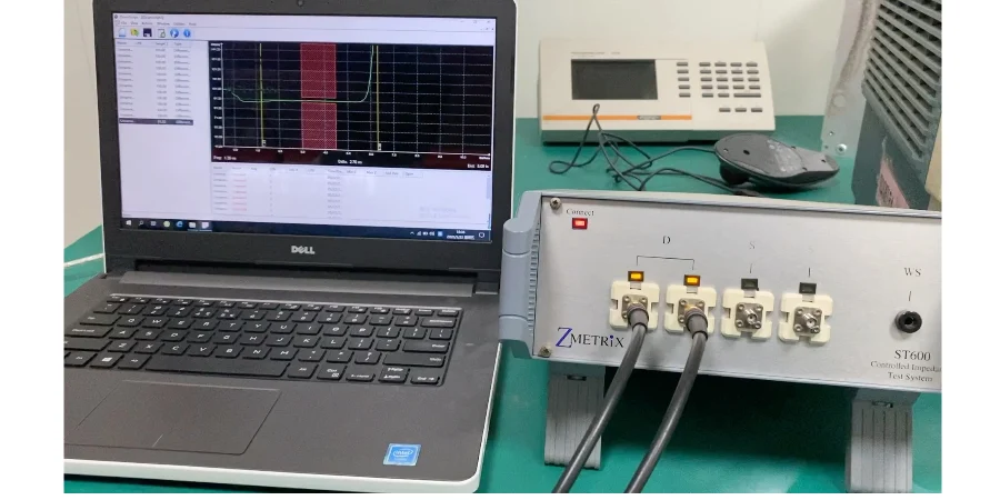
- Definition: the percentage of impedance coupons measured by TDR whose actual impedance falls within design tolerance (e.g., ±5%).
- Target: >98%.
- Improvement: a direct measure of design–manufacturing collaboration. HILPCB’s impedance test reports provide the key data for closing the loop.
- NPI Cycle Time:
- Definition: time from file release to receiving a fully functional prototype.
- Target: shorten by 15% through standardized deliverables and efficient DFM communication.
- Improvement: identify bottlenecks—often repeated clarification due to non-standard files.
8. HILPCB collaboration services and case
Challenge: a leading communications equipment company developing a next-generation high-speed switch saw severe signal jitter and random packet loss. Logic design and simulation passed, but prototype performance was far below target. Root cause: excessive rail noise on the 400Gbps SerDes channel; the traditional decoupling strategy completely failed.
HILPCB solution:
- Deep co-design: HILPCB FAE worked with the customer from the very front end. We didn’t start by swapping capacitors; we rebuilt the 20-layer stackup using ultra-thin cores, compressing the spacing between key PWR and GND layers from 6mil to 2.5mil—greatly boosting plane capacitance.
- Target-driven PI simulation: with Sigrity PowerSI, we set a target impedance below 5mΩ at 1GHz for key SerDes rails. After hundreds of iterations, we optimized a mix of capacitors from 0201 to 1210 packages, forming a broadband, low-impedance PDN.
- DFM-driven physical implementation: during placement, we used the HILPCB DFM rule library to guide via design under the BGA, minimizing connection inductance per decap while ensuring 100% manufacturability.
- Closed-loop validation: in production, we ran incoming Dk/Df inspection on every lot and built dedicated PDN impedance coupons. The final deliverable was not only the PCB, but also a detailed test report proving PDN impedance matched simulation.
Result: with HILPCB’s co-design and manufacturing plan, the customer’s second revision passed all performance tests in one shot and launched successfully—cutting nearly two months from the schedule. This case proves that a scientific, manufacturing-integrated pcb design process is the only way to solve complex PI challenges.
Bring us your next high-difficulty project. HILPCB is not just a vendor—it’s your partner for design success.
Conclusion
This article targets design leads and uses decoupling network basics to provide a process framework, stackup/routing strategies, DFM/DFT checklists, and deliverable templates—helping teams control risk across design, materials, and test. By executing the checklist and process window, and involving HILPCB’s DFM/DFA team early, you can accelerate prototypes and mass production while maintaining quality and compliance.
For manufacturing and assembly support, contact HILPCB Turnkey Assembly or SMT Assembly for DFM/DFT recommendations.