
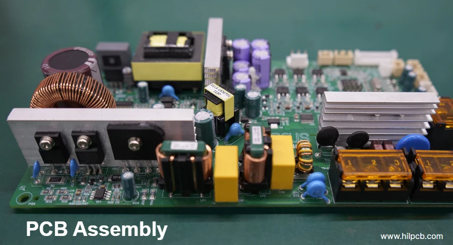
With the surge of AI and HPC, chip design is moving faster than ever toward Chiplet heterogeneous integration and 2.5D/3D packaging. While this shift unlocks massive compute gains, it also creates major design and manufacturing challenges for the underlying AI chip interconnect and IC substrate PCB. From hundreds of watts of power to Tb/s‑class I/O bandwidth, every design decision directly impacts final performance, cost, and reliability. In this complex ecosystem, a comprehensive DFM/DFT/DFA review (Design for Manufacturability/Testability/Assembly) is no longer optional—it is a core pillar of project success. It bridges design, manufacturing, and assembly, systematically identifying and eliminating latent risks.
For teams building cutting‑edge AI hardware, a rigorous DFM/DFT/DFA review process is what enables a smooth transition from prototype to volume production. It spans everything from material selection and stack‑up optimization to high‑speed signal integrity, PDN, and thermal management. Experienced manufacturers like Highleap PCB Factory (HILPCB) embed this review across the entire lifecycle—from design consultation through final assembly—helping customers navigate complex packaging challenges and bring advanced designs to production with high yield and reliability.
What is the core value of DFM/DFT/DFA review in AI chip packaging?
In traditional PCB design, DFM, DFT, and DFA may be treated as separate checks. In AI IC substrates and advanced packaging, they are tightly coupled and inseparable. Together they form a unified risk‑assessment and optimization framework—balancing performance, cost, yield, and time‑to‑market.
- DFM (Design for Manufacturability): Focuses on physical realizability. For AI substrates, the goal is to ensure ultra‑fine features (e.g., 2/2µm RDL), high‑aspect‑ratio Microvia, and complex multi‑layer stacks can be manufactured stably with high yield. This directly impacts manufacturing cost and cycle time—especially for ultra‑precision projects like CoWoS carrier substrate low volume builds where consistency and accuracy are critical.
- DFT (Design for Testability): Focuses on how well the product can be tested. As Chiplet counts rise and I/O density explodes, conventional test methods don’t scale. DFT must introduce Test Point, Boundary Scan paths, and BIST logic early in the design so connection defects, electrical faults, and functional issues can be detected efficiently after manufacturing and assembly. This is essential for effective RDL fan-out substrate validation.
- DFA (Design for Assembly): Focuses on packaging and assembly feasibility. Beyond accurate placement of Chiplet and HBM, DFA evaluates processes such as TCB, Underfill, and BGA ball attach. It considers component spacing, pad design, substrate warpage control, and thermal behavior to avoid yield loss and reliability problems during assembly.
Their combined effect ensures the design is not only theoretically sound, but also manufacturable and assemble‑able in the real world. A strong DFM/DFT/DFA review can surface more than 90% of potential manufacturing/assembly issues early—dramatically shortening time‑to‑market and lowering total project cost.
How does DFM protect high-speed signal integrity for Chiplet interconnect?
In the PCIe 6.0 and HBM3e era, signal integrity (SI) is a primary challenge for AI substrate design. Thousands of high‑speed interconnect channels between Chiplet behave like fragile nerves—any small manufacturing deviation can distort signals, cause data errors, or even crash the system. DFM acts as the “guardian” in this phase.
First, DFM ensures precise impedance control. Differential targets like 50Ω or 90Ω must be reproduced in manufacturing. That requires co‑analysis of trace width, dielectric thickness, copper thickness, and the Dk/Df of the selected Chiplet bridge PCB materials. HILPCB’s DFM flow uses advanced field‑solver tools plus extensive high-speed PCB manufacturing experience to simulate the customer design and recommend optimizations based on real process parameters—keeping impedance variation within ±5%.
Second, DFM focuses on discontinuities in the channel. Microvia, layer‑transition vias, and BGA pads are potential impedance discontinuities that introduce reflections and loss. Through DFM review, via structures (e.g., backdrill or via fill), pad design (NSMD vs. SMD), and routing paths can be optimized to minimize discontinuity penalties. For dense structures like Chiplet bridge PCB, DFM pays special attention to the interconnect region between the bridge die and the substrate to ensure electrical performance meets ultra‑high‑speed requirements.
Finally, crosstalk control is another DFM priority. At extreme routing density, electromagnetic coupling between adjacent traces can severely degrade signal quality. DFM evaluates trace spacing, reference‑plane continuity, and shielding effectiveness—and proposes targeted improvements such as increased spacing, guard traces/ground shields, or Stripline routing to keep critical channels clean.
How important is DFA for thermal management and power integrity?
AI chip power has reached hundreds of watts—and in many cases, over a kilowatt. That makes thermal management and power integrity (PI) as critical as SI. DFA (Design for Assembly) is vital here because it directly determines whether the chip can receive stable power and dissipate heat effectively in real operation.
On the thermal side, DFA reviews the full heat‑flow path from die to heatsink, including:
- TIM (Thermal Interface Material) selection and application: evaluating thickness, coverage, and dispensing/press processes to ensure the TIM fills micro‑gaps between die and heatsink and reduces thermal resistance.
- Component placement: placing high‑power Chiplet and HBM to avoid excessive hotspot concentration. DFA combines thermal simulation results to recommend optimal placement for more uniform heat spreading.
- Cooling-structure integration: evaluating the install feasibility of heatsinks, vapor chambers, or liquid‑cooling modules—including mounting holes, pressure uniformity, and mechanical stress—so the post‑assembly solution performs as intended.
On the power‑integrity side, DFA works closely with DFM to ensure the PDN can handle large transient current demands:
- Decoupling capacitor placement: ensuring decaps are as close as possible to AI SoC power pins to minimize loop inductance and suppress high‑frequency noise and droop.
- Power/GND layer design: jointly reviewing plane partitioning, copper thickness, and via count/placement to provide low‑impedance current paths.
- Assembly-process impact: considering how soldering affects PDN performance—for example, BGA voiding can increase resistance/inductance in the power path and degrade power quality.
A thorough DFA review ensures the AI chip not only powers on, but also runs stably at peak performance long‑term—avoiding throttling or system crashes caused by overheating or unstable power.
💠 Key performance monitoring dashboard for AI IC substrates (Advanced IC Substrate)
For 2.5D/3D packaging, monitor PDN, signal integrity, and physical-stress limits in real time.
PDN target impedance (Z-Target)
< 1 mΩ
@ >100MHz band / meets transient demand
Transient voltage ripple (Ripple)
< 3% VDD
Protects voltage margin for core compute units
Junction temperature control (Tj)
< 105°C
Integrated heat-spreader design and microchannel cooling
HBM3/4 insertion loss
< -3 dB
@ Nyquist Freq / ultra-high-speed memory access
Substrate warpage (Warpage)
< 5 µm/mm
For Large Body Size assembly yield
Microvia TCT lifetime
> 1k Cycles
Meets ultra‑stringent JEDEC reliability standards
What are the key DFT considerations in complex AI substrate design?
As packaging density and complexity increase, effective test of AI substrates becomes extremely difficult. Many internal nodes are inaccessible after assembly, making DFT (Design for Testability) the only practical way to ensure product quality and diagnose failures.
An effective DFT strategy starts in the design phase and typically includes:
- Boundary Scan (IEEE 1149.1/JTAG): the most fundamental DFT technique. By integrating boundary‑scan cells on each Chiplet’s I/O pins, you can test Chiplet‑to‑Chiplet and Chiplet‑to‑substrate interconnect without physically probing pins. DFT review verifies the JTAG chain’s completeness and signal quality so it can be accessed smoothly during production test.
- Internal scan and BIST (Built-In Self-Test): for Chiplet internal logic, DFT drives the inclusion of scan chains and BIST circuits so the device can “self test” and report results through JTAG—greatly improving coverage and efficiency.
- TAP (Test Access Port) design: ensuring TAP is designed to connect to test equipment easily. In volume production this may require dedicated fixture interfaces for ATE.
- Failure diagnosis capability: good DFT doesn’t just indicate pass/fail—it provides actionable diagnosis. For example, analyzing scan‑chain fail data can pinpoint which interconnect has an open or short. This is critical to failure analysis during RDL fan-out substrate validation, enabling faster process tuning.
At HILPCB, our DFT review is tightly integrated with DFM and DFA. We work with customer design teams to align the DFT strategy with our manufacturing capabilities and assembly services, delivering the most efficient and cost‑effective end‑to‑end test plan.
How does DFM enable microvia HDI stack cost optimization?
Microvia and HDI are the foundation of modern AI substrates, but they are also a major cost driver. With careful DFM review, you can achieve meaningful microvia HDI stack cost optimization—reducing manufacturing cost without sacrificing performance.
The key lever is the stack‑up. Different structures—such as 1+N+1, 2+N+2, or ELIC—have very different cost profiles. DFM review analyzes and optimizes from several angles:
- Layer count and material selection: whether you can reduce signal or power layers while still meeting SI/PI requirements. Based on data rate and loss budget, select the most cost‑effective substrate materials. Not every layer needs an expensive ultra‑low‑loss dielectric—using standard materials in non‑critical layers controls cost.
- Microvia stacking strategy: Stacked Microvias deliver the highest routing density, but each additional stacked level increases complexity and cost dramatically. DFM evaluates routing density and explores replacing some stacked Microvias with Staggered Microvias—often lowering cost and improving yield with minimal routing penalty.
- Process capability matching: the essence of DFM is matching design to real fabrication capability. For example, HILPCB’s advanced mSAP (modified Semi-Additive Process) enables finer line/space. Leveraging that can reduce layer count and deliver microvia HDI stack cost optimization. We also present clear cost‑performance tradeoffs to support better decisions.
Through this structured analysis, DFM is not just error correction—it is value creation, helping teams gain cost advantage in highly competitive markets.
HDI stack strategy comparison
| Attribute | Standard HDI (Staggered) | Stacked HDI (Stacked) | ELIC (Every-Layer Interconnect) |
|---|---|---|---|
| Routing density | High | Very high | Ultra-high |
| Manufacturing cost | Baseline | High (~1.5x) | Very high (~2.5x+) |
| Manufacturing yield | High | Medium | Relatively low |
| Reliability | Very high | High (requires strict process control) | High (requires top-tier process control) |
| Best-fit scenarios | Most HPC/AI applications | Ultra-high-density routing under BGA regions | Flagship smartphones and wearables |
What unique manufacturing challenges does Chiplet bridge PCB face?
Chiplet bridge PCB, whether silicon-based (EMIB) or organic, represents the cutting edge of today’s interconnect technology. It integrates thousands of ultra‑fine‑pitch interconnect lines into a tiny area—creating unprecedented manufacturing difficulty and a major focus area for DFM/DFT/DFA review.
- Ultra-fine line fabrication: line/space is often below 10µm, far beyond conventional PCB capability. This requires mSAP or SAP processes, with extremely tight control of lithography, etching, and plating. DFM review must ensure design rules match the manufacturer’s real process window.
- Material selection and stability: choosing Chiplet bridge PCB materials is critical. Low CTE, high Tg, and excellent dimensional stability reduce deformation and stress during lamination and thermal cycling. DFM evaluates performance/cost tradeoffs and recommends the best-fit material set.
- Layer-to-layer alignment accuracy: at the micron scale, registration accuracy drives yield. Small offsets can prevent Microvia from landing on target pads. Fabrication requires high‑precision alignment and strict process control, and DFM ensures design margin (e.g., pad size) can absorb realistic tolerances.
- Embedded processes: many bridges are embedded inside the organic substrate, involving cavity formation, die placement, plating/planarization, and surface flattening. DFA review evaluates the feasibility and reliability of these assembly steps to avoid damage or new defect modes.
Meeting these challenges requires early, deep collaboration between the design team and an advanced supplier like HILPCB with strong IC substrate capability. A front‑loaded DFM/DFT/DFA review helps eliminate manufacturing traps before design freeze.
How does RDL fan-out substrate validation integrate into DFA?
Fan-out packaging—especially RDL (Redistribution Layer) based wafer‑level/panel‑level fan‑out—is another key route to high‑density I/O and heterogeneous integration. RDL fan-out substrate validation is the critical step to ensure such packages succeed, and it is inseparable from DFA.
Validation is not just electrical test—it is a holistic assessment across design, materials, process, and assembly. DFA plays the central role:
- RDL design-rule checks: reviewing RDL layout—line/space, via design, and pad shapes—to ensure compatibility with assembly processes. For example, UBM (Under Bump Metallurgy) must match ball‑attach processes to form reliable joints.
- Warpage simulation and control: fan‑out packages suffer warpage due to CTE mismatch among silicon, epoxy, and copper in reconstituted wafers/panels. DFA includes thermo‑mechanical simulation to predict warpage during reflow and optimize copper distribution, polymer selection, and structure to keep warpage within limits.
- Reliability test planning: based on DFA insights, teams can predict weak points such as stress concentration at RDL corners or tiny solder joints. This enables targeted reliability plans—TCT, HAST, drop tests—to complete robust RDL fan-out substrate validation.
By pushing validation left into the DFA phase, you avoid discovering fatal design issues only after investing in expensive masks and production resources—accelerating development and increasing success rates.
HILPCB advanced IC substrate manufacturing capability matrix
| Parameter | Standard capability | Advanced capability (HILPCB) | Technical advantage |
|---|---|---|---|
| Minimum line/space | 15/15 µm | 5/5 µm (mSAP) | Supports ultra-high-density RDL and Chiplet interconnect |
| Minimum microvia diameter | 75 µm | 25 µm (UV Laser) | Enables extreme I/O density |
| Max layer count | 16 layers | 30+ layers | Meets complex PDN and signal-routing needs |
| Impedance control accuracy | ±10% | ±5% | Protects HBM/PCIe Gen6 signal integrity |
| Substrate materials | Standard FR-4, High Tg | ABF, BT, Low Dk/Df materials | Supports high-speed, high-reliability applications |
How to define a DFM strategy for CoWoS carrier substrate low-volume production?
CoWoS (Chip-on-Wafer-on-Substrate) is a mainstream 2.5D packaging technology widely used in top-tier AI accelerators. For CoWoS carrier substrate low volume builds—prototype validation, NPI, or niche products—DFM must balance fast iteration, cost control, and risk management.
- Prioritize design robustness: in low-volume phases, robustness matters more than extreme cost optimization. DFM often recommends more relaxed rules (slightly wider line/space and larger pads) to maximize first-pass success, so teams can quickly get functional samples for system validation.
- Modular and platform-based design: where possible, use a modular approach—decouple high‑risk, high‑density CoWoS areas from more conventional I/O and power regions. This enables partial respins in later iterations instead of redesigning the full substrate.
- Choose a flexible manufacturing partner: low-volume builds demand responsiveness and strong engineering support. Companies like HILPCB run dedicated rapid‑turn and NPI lines and can provide customized services and fast technical feedback for CoWoS carrier substrate low volume programs.
- Comprehensive simulation and virtual prototyping: detailed SI/PI/thermal/mechanical‑stress simulation before fabrication is core to low‑volume DFM. “Virtual manufacturing” and “virtual testing” catch most issues in the design phase and avoid expensive physical trial‑and‑error.
This risk‑focused, iteration‑friendly DFM strategy supports low-volume CoWoS development and lays the foundation for future high-volume production.
Conclusion: Use comprehensive DFM/DFT/DFA review to manage what comes next
The future of AI chips will be built on even more advanced packaging and interconnect. Whether Chiplet, 3D stacking, or co-packaged optics, complexity will keep rising. In this context, a systematic, forward-looking DFM/DFT/DFA review is the essential link between innovative design and reliable manufacturing. It is no longer a last-step checkpoint—it is a collaborative engineering discipline that runs end‑to‑end.
By deeply understanding every detail of manufacturing, testing, and assembly—from Chiplet bridge PCB materials selection to microvia HDI stack cost optimization strategies, and robust execution of RDL fan-out substrate validation—teams can reduce risk, accelerate time‑to‑market, and win in highly competitive markets.
As your trusted partner, HILPCB provides industry‑leading HDI PCB and IC substrate manufacturing services. Our experienced engineering team works closely with you through a rigorous DFM/DFT/DFA review process—turning your most challenging designs into high‑performance, high‑reliability products. Contact us to kick off your next AI innovation program.
Common Questions
Why is DFM/DFT/DFA review so strategic for AI chip interconnect projects?
Advanced AI packaging combines extreme density, thermal stress, fine-feature manufacturing, and difficult test access in one program. A structured review is what keeps those risks visible and manageable across design, validation, and production.
Why must signal integrity, power integrity, thermal design, and manufacturability be reviewed together?
These designs are too interconnected to optimize one area in isolation. A change made for routing density or thermal relief can easily affect yield, testability, or high-speed channel behavior somewhere else in the package.
Why does low-volume or NPI strategy matter so much for advanced AI substrates?
Prototype and early production phases need fast learning without absorbing unnecessary respin cost. A review strategy focused on robustness, simulation, and realistic process capability gives teams a better path into later scale-up.
Why should teams involve an experienced substrate manufacturing partner early?
Substrate and advanced interconnect projects depend on real process knowledge, not just design intent. A capable partner can guide rules, risk trade-offs, and validation priorities before the project locks itself into an unbuildable direction.