
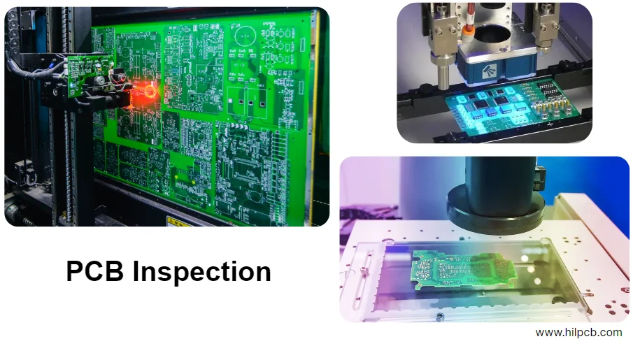
Hi, I’m an instructor at HILPCB Manufacturing Academy. In high-performance electronics, design matters—but the “last mile” is manufacturing and test: converting CAD data into a real, reliable PCBA. Many oversights in DFM/DFT eventually show up as expensive rework and delayed time-to-market.
Today we’ll use a key reliability test—hipot test procedure (dielectric withstand / high-voltage test procedure)—as the anchor to walk through the entire PCB fabrication + assembly flow. This is not just a list of pcb fabrication process steps; it’s a practical guide aimed at building a real yield improvement roadmap. Starting from incoming materials, we’ll go through imaging, drilling/plating, SMT, and finally strict verification—showing the quality control points and the “design ↔ manufacturing” collaboration tips at each stage.
Manufacturing at a glance: from design data to finished PCBA
Before diving into details, let’s look at the end-to-end flow from bare-board fabrication to PCBA assembly and test. Understanding the full picture is the basis for an effective DFM/DFT strategy.
| Process stage | Core objective | Key control parameters | Related DFM/DFT points |
|---|---|---|---|
| 1. Engineering & incoming materials | Translate design data, prepare base materials | CAM data check, laminate selection (FR-4, Rogers), copper thickness | Stackup documentation guide, impedance control, material Dk/Df |
| 2. Inner-layer imaging | Form inner-layer circuitry | Exposure energy, develop time, etch rate, line width/spacing tolerance | Copper balance, avoid acute corners, inner-layer clearance |
| 3. Lamination | Press cores + prepregs into a stack | Temperature/pressure/time profile, registration (X-Ray) | Symmetry, avoid overly dense buried/blind via regions |
| 4. Drilling | Create vias and component holes | Spindle/feed, position accuracy (±0.05mm), wall roughness | Hole tolerance, annular ring, remove non-functional pads |
| 5. PTH copper & plating | Build interlayer electrical connection | Desmear, electroless copper, plated copper thickness (>20µm), uniformity | Aspect Ratio (thickness/hole dia) < 10:1, avoid via-in-pad |
| 6. Outer-layer imaging & solder mask | Form outer circuitry, protect non-solder areas | Etch compensation, solder mask registration, solder mask dam width | Mask opening sizing, BGA pad definition (SMD/NSMD) |
| 7. Surface finish & profiling | Improve solderability, routing/profiling | ENIG Au thickness (2–4µ"), HASL flatness, V-cut/CNC accuracy | Finish selection, panelization, tooling edge design |
| 8. SMT assembly | Place and solder components | Paste volume (SPI), placement accuracy, reflow profile | SMT stencil design tutorial, spacing, fiducials |
| 9. Test & verification | Ensure electrical performance and reliability | ICT/FCT coverage, Hipot Test voltage/time, X-Ray inspection | Test point design, high-voltage creepage/clearance |
Control points for imaging, etching, and solder mask
Circuit feature accuracy directly determines electrical performance. At HILPCB we run tight process windows to reproduce design intent consistently.
Imaging & etching
The core of imaging is to transfer CAM-processed patterns onto copper via a photochemical process.
- Dry film & exposure: We use high-resolution dry film and LDI (laser direct imaging) instead of film, eliminating film expansion/shrink registration error and improving edge definition.
- Etch control: Etching is a subtractive process—removing unwanted copper. Poor control causes over-etch (thin lines) or under-etch (thick lines/shorts).
Process window: high-precision etching
- Etching factor: > 3.5, ensuring steep sidewalls and a trapezoid cross-section (not “mushroom”).
- Line width tolerance: for 4mil/4mil, keep within ±15%.
- Automation control: automatic dosing + real-time concentration/temperature monitoring to stabilize etch rate.
DFM tips:
- Copper balance: keep copper distribution even per layer; avoid large solid copper next to sparse traces to reduce etch non-uniformity and warpage.
- Avoid acute corners: sharp corners (<90°) can trap chemistry and cause over-etch; use arcs or 45° corners instead.
Solder mask
Solder mask is not just the “green jacket”—it prevents bridging and protects circuitry.
- Registration accuracy: critical for fine pitch (e.g., 0.4mm pitch BGA). We use fully automatic CCD alignment exposure; typical alignment capability reaches ±25µm.
- Solder mask dam: for IC pins, keep the dam intact/strong. Recommended minimum dam width ≥ 75µm (3mil) for manufacturability.
Quality control for drilling, plating, and PTH copper
Vias are the “vertical highways” of multilayer boards; their quality impacts SI and product lifetime.
Drilling
- Mechanical drilling: for most through-holes we use high-speed CNC drilling and control tool life (e.g., change every 2000 hits) to maintain wall quality.
- Laser drilling: for HDI microvias, CO₂ or UV laser drilling is used; diameters can be as small as 75µm.
PTH copper & plating (PTH)
After drilling, the hole wall is resin + glass (non-conductive). PTH (Plated Through-Hole) metallizes it for interconnect.
- Desmear & electroless copper: remove smear, then deposit a thin electroless copper seed.
- Pattern plating: electroplating builds copper on traces and in holes.
Process window: high-reliability PTH copper
- PTH copper thickness: average > 20µm (0.8mil), aligned with IPC Class 2/3 expectations for conductivity and thermal shock robustness.
- Aspect ratio: for high AR holes (e.g., 12:1), special chemistry + pulse plating keep center-to-surface thickness difference < 30%.
- Microsection analysis: metallographic cross-sections per lot to verify thickness, uniformity, and wall quality.
DFM tips:
- Optimize aspect ratio: avoid overly high AR designs; they sharply increase plating difficulty and cost.
- Pad design: keep sufficient annular ring after drilling; IPC commonly recommends ≥ 50µm minimum to ensure robust connection.
SMT process control: paste, placement, and reflow
PCBA quality is half bare board, half SMT (Surface Mount Technology) assembly.
Solder paste printing
Over 60% of solder defects originate from printing—this is the first and most critical SMT step.
- Stencil design: a strong smt stencil design tutorial emphasizes aperture design. We tailor apertures to component/pad geometry; for BGA/QFN we apply anti-solder-ball designs (e.g., U-shape, “crescent”).
- SPI (Solder Paste Inspection): every board is 100% inspected by 3D SPI to measure volume/area/height/offset, preventing insufficient/excess paste and bridging from the start.
Pick & place and reflow
- Pick & place: high-speed placement machines deliver accuracy, but our MES + smart storage also enforces poka-yoke and traceability—ensuring the right part at the right location.
- Reflow soldering: the reflow profile is the “soul” of solder quality. We build a product-specific profile based on PCB size/thickness/layer count and component density.
Process window: lead-free reflow profile
- Preheat: 150–200°C, 60–120s; activates flux and reduces thermal shock.
- Soak: 200–217°C, 60–90s; equalizes board temperature.
- Reflow: peak 240–250°C; time above liquidus (217°C) for 45–75s.
- Cooling: ramp < 4°C/s; promotes good solder joint grain structure.
Cleaning, conformal coating, and reliability processing
For high-reliability products or harsh environments, post-processing matters.
- Cleaning: flux residues may contain active ions; in heat/humidity they can drive electrochemical migration and shorts. We use aqueous + ultrasonic cleaning and quantify cleanliness via Ion Chromatography or ROSE testing, targeting industry limits (e.g., IPC-J-STD-001 <1.56µg/cm² NaCl equivalent).
- Conformal coating: a transparent polymer layer protects against humidity, salt fog, and mold. We provide automated selective coating to precisely control area and thickness while avoiding connectors and other keep-out zones.
Test matrix: from inline inspection to high-voltage verification
Testing is not a single step—it’s a matrix aimed at finding defects early and lowering repair cost.
| Test type | Stage | Objective & coverage | Key equipment/method |
|---|---|---|---|
| AOI | After reflow | Presence, wrong part, polarity, offset, visible solder quality | High-res cameras + image comparison |
| SPI | After printing | Paste volume/area/height/offset | 3D laser scan |
| X-Ray Inspection | After reflow | Hidden joints (BGA/QFN/LGA): opens, shorts, voids | 2.5D / 3D X-Ray |
| ICT | After assembly | Component values, opens/shorts | Bed-of-nails or flying probe |
| FCT | After assembly | Simulate real operation; verify functions | Custom fixtures, LabVIEW/Python |
| Hipot Test | After PCBA/final assembly | Verify insulation strength; prevent breakdown/leakage | Hipot tester + safety enclosure |
Deep dive: Hipot test procedure
Hipot (dielectric withstand) is a core safety and reliability test. It applies a voltage far above normal operation to stress the insulation system. A failure may indicate latent shorting, electric shock risk, or fire hazard. The materials and spacing that set that insulation system are covered in PCB insulation design guidelines.
Standard operating procedure (SOP): Hipot Test
- Safety preparation: Operators wear insulating gloves; set safety warnings. Place the DUT in an insulated fixture or safety box.
- Instrument setup: Connect the hipot tester and set parameters per spec. For a 220V AC power board, the test may be 1500V AC or 2121V DC.
- Parameter configuration:
- Voltage: 1500V AC
- Ramp-up time: 3s (avoid impulse stress)
- Dwell time: 60s (typical safety requirement)
- Leakage current limit: 5 mA
- Connect the DUT: Connect HV to the primary (e.g., AC L/N) and return/ground to secondary ground and chassis (protective earth), stressing primary-to-secondary and primary-to-earth insulation.
- Run the test: Start the program. The instrument ramps, dwells, and measures automatically. Operators must not touch the DUT during the test.
- Pass/fail decision:
- PASS: leakage stays below 5mA with no arcing/breakdown during dwell.
- FAIL: leakage exceeds limit or breakdown occurs; the instrument cuts HV and alarms.
- Record & discharge: log results; the instrument discharges internal capacitors to ensure safety.
Deep dive: X-Ray inspection checklist
For bottom-terminated packages like BGA/QFN, AOI cannot “see” the joints—X-Ray becomes the only way to inspect.
- [ ] Shorts: are adjacent balls bridged?
- [ ] Opens / head-in-pillow: is the ball fully fused to the pad? Any “Head-in-Pillow”?
- [ ] Joint size/shape: is collapse uniform?
- [ ] Voiding: is void area > 25% (IPC-A-610 guideline)?
- [ ] Alignment: is the component centered on pads?
HILPCB’s 3D X-Ray can locate defects via tomography and feed data back to process optimization.
Quality and traceability: the power of data
Great manufacturing is not just “build a good board”—it’s a system that continuously improves and stays fully traceable.
- SPC: real-time monitoring of key variables (reflow temperature, plating chemistry concentration, etc.) with control charts to shift from “after-the-fact detection” to “before-the-fact prevention”.
- MES: from PCB part number/batch to every SMT reel, plus operator and equipment IDs at each station—everything is recorded. A unique QR code links the full genealogy of each PCBA.
- 8D report: for batch issues, we run an 8D process for root cause, corrective and preventive actions, and share the closed-loop report with customers.
A strong manufacturing partner doesn’t just deliver quality hardware—it delivers transparent, traceable data to help you iterate and build your yield improvement roadmap.
Ready to raise your product reliability?
From complex HDI designs to high-reliability assembly and test, HILPCB provides a one-stop solution. Our DFM/DFT engineering team is ready to work with you early—preventing manufacturing risks before they happen. Upload your Gerber and BOM to get a free DFM review and a quote.
Get a free DFM reviewHILPCB’s integrated manufacturing + test capability
As your manufacturing partner, HILPCB invests not only in top-tier equipment but also in a data-driven, transparent smart manufacturing platform.
In short, a rigorous hipot test procedure is only one visible part of high-quality PCBA manufacturing. True reliability comes from disciplined control of every detail in pcb fabrication process steps. At HILPCB, we turn that control into standardized processes, data-driven management, and professional service—ready to build products that stand up to real-world tests.
Conclusion
This article used the hipot test procedure as the anchor to walk through the end-to-end flow—from incoming materials and imaging to solder mask, SMT, and final verification—highlighting manufacturing details, quality control points, and actionable DFM/DFT practices. If you execute with the checklists and process windows above, and involve HILPCB’s DFM/DFA team early, you can accelerate prototype-to-production delivery while protecting quality and compliance.
For PCB fabrication and assembly support, contact HILPCB Turnkey Assembly or SMT Assembly for DFM/DFT guidance.
Common Questions
What does a hipot test verify on a PCB or PCBA?
A hipot test verifies that insulation barriers can withstand a specified high voltage without breakdown or excessive leakage current. It is commonly used to confirm dielectric strength between isolated nets, power domains, or user-accessible circuitry.
Why is hipot testing only one part of overall manufacturing quality?
Because a product can pass hipot and still fail later due to weak drilling quality, plating defects, solder mask issues, or assembly problems. Real reliability depends on process control across the full fabrication and PCBA flow.
When should engineers think about hipot requirements during design?
They should consider them early, especially when defining creepage, clearance, isolation slots, stackup, and test access. Waiting until the final verification stage often leads to redesign or expensive process changes.
What should be validated before releasing a high-voltage PCB into production?
Teams should validate insulation spacing, plated-through-hole quality, cleanliness, coating strategy, and the final hipot test window. Good DFM/DFT preparation makes the final verification step much more predictable.