
In printed circuit board design and electronics manufacturing, IPC standards represent the universal technical framework that defines design rules, material specifications, fabrication tolerances, and assembly acceptance criteria. Understanding what is IPC and how its tiered standards govern each lifecycle stage is vital for hardware engineers, procurement specialists, and quality auditors.
Without IPC standards, the global electronics supply chain could not function. They establish unambiguous contract terms between original equipment manufacturers (OEMs), bare-board PCB fabricators, and electronic manufacturing services (EMS) providers, ensuring consistent quality, mechanical durability, and electrical safety.
What Does "IPC" Stand For? (IPC Meaning & History)
IPC stands for the Association Connecting Electronics Industries, though the acronym originated historically in 1957 as the Institute for Printed Circuits.
As electronic packaging evolved beyond simple single-sided wiring boards to complex hybrid microelectronics, flexible substrates, and advanced surface-mount assemblies, the association renamed itself in 1977 to the Institute for Interconnecting and Packaging Electronic Circuits. By 1999, because the original full name was cumbersome, the organization formally adopted IPC as its official legal name, accompanied by the operational trademark: "Association Connecting Electronics Industries".
Today, IPC is an ANSI-accredited standards-developing trade association with over 3,000 member companies worldwide. It publishes hundreds of consensus-driven industrial standards covering every discipline of electronic interconnect technology.
IPC Standard Classes: Class 1 vs. Class 2 vs. Class 3
IPC standards categorize electronic products into three primary performance classes based on expected operational lifetime, operational duty cycles, and environmental severity:
IPC Class 1: General Electronic Products
- Scope: Consumer electronics, toys, gaming peripherals, and low-cost consumer appliances.
- Criteria: The major requirement is the complete functionality of the final assembled device. Cosmetic surface imperfections, minor misalignments, or non-critical solder voids are permitted. Extended lifetime is not a requirement.
IPC Class 2: Dedicated Service Electronic Products
- Scope: Industrial automation controllers, telecommunication equipment, commercial computing servers, and home appliances.
- Criteria: Requires continuous operational reliability and extended lifecycle. Uninterrupted service is desired but not strictly life-critical. Controlled cosmetic standards and strict electrical tolerances are enforced. This is the default manufacturing tier for commercial hardware.
IPC Class 3: High Performance / Harsh Environment Electronic Products
- Scope: Medical life-support equipment, aerospace flight control, defense munitions, space avionics, and automotive safety systems (e.g., ADAS, braking controllers).
- Criteria: Continued operational performance or performance-on-demand is absolutely mandatory. Equipment downtime cannot be tolerated, and products must operate reliably in hostile operating environments (thermal shock, high vibration, extreme humidity). 100% inspection, zero-defect acceptance, and thicker barrel plating are mandatory.
| Comparison Parameter | IPC Class 1 | IPC Class 2 | IPC Class 3 |
|---|---|---|---|
| Typical Products | Toys, remote controls, disposable electronics | Industrial PCs, telecom switches, power supplies | Pacemakers, aircraft avionics, missile guidance |
| Operational Downtime | Acceptable / non-critical | Minimal downtime acceptable | Strictly zero tolerance for downtime |
| Through-Hole Barrel Copper Plating | Average 18 µm (0.7 mil) | Average 20 µm (0.8 mil) | Average 25 µm (1.0 mil), Min 20 µm |
| Annular Ring Requirement | 0 mil breakout permitted (90° max) | Minimum 90° breakout permitted, 180° supported | Zero breakout permitted; min internal annular ring 2 mils (50 µm) |
| Through-Hole Vertical Solder Fill | Not specified (function only) | Minimum 50% vertical barrel fill | Minimum 75% vertical barrel fill |
| Inspection Rigor | Visual sample check | AOI + AQL statistical sampling | 100% AOI, 100% Electrical Test, Microsection coupon test |
The Core IPC Standards Family: Design, Fabrication, and Assembly
The IPC standards ecosystem is architected around the physical progression of hardware manufacturing: from schematic layout, to bare laminate fabrication, through SMT solder assembly.
+---------------------------------------------------------------+
|                    IPC Standards Architecture                 |
+---------------------------------------------------------------+
| 1. Design & Layout:       IPC-2221, IPC-2222, IPC-7351         |
| 2. Base Materials:        IPC-4101, IPC-4204, IPC-4562         |
| 3. Bare Board Fab:        IPC-6012 (Rigid), IPC-6013 (Flex)   |
| 4. Bare Board Acceptance: IPC-A-600                            |
| 5. SMT & Assembly:        J-STD-001, IPC-A-610, IPC-7711/7721  |
| 6. Storage & Moisture:    IPC-1601, J-STD-033                  |
+---------------------------------------------------------------+
1. Design Standards (The 2220 & 7350 Series)
- IPC-2221 (Generic Standard on Printed Board Design): The foundational design guideline. Defines electrical clearance vs. voltage rules, thermal dissipation spacing, test point placement, and trace current-carrying capacity charts (originally derived from IPC-2152).
- IPC-2222: Sectional design standard for rigid organic printed boards, providing dielectric thickness and aspect ratio limits.
- IPC-7351: Generic requirements for surface mount design and land pattern standards. Provides mathematical models to generate reliable component footprints, solder fillet expectations, and pin-1 zero-orientation rules.
2. Base Material Standards (The 4000 Series)
- IPC-4101 (Specification for Base Materials for Rigid and Multilayer Boards): The worldwide procurement catalog for copper-clad laminates (CCL) and prepregs. Categorizes materials by "slash sheets" (e.g., /21, /24, /126 for high-Tg FR-4), defining glass transition temperature ($T_g$), decomposition temperature ($T_d$), and comparative tracking index (CTI).
- IPC-4204: Specification for flexible metal-clad dielectrics (polyimide films for flex circuits).
- IPC-4562: Metal foil specifications for printed wiring applications (electrodeposited and rolled annealed copper foils).
3. Fabrication & Performance Standards (The 6010 Series)
- IPC-6011: Generic performance specification for printed boards, establishing baseline requirements across all board constructions.
- IPC-6012 (Qualification and Performance Specification for Rigid Printed Boards): The critical standard for bare-board manufacturers. Defines plating thickness, thermal stress survivability, copper adhesion, delamination resistance, and microsection coupon evaluations for Class 1, 2, and 3.
- IPC-6013: Qualification and performance specification for flexible and rigid-flex printed wiring.
4. Bare Board Inspection & Acceptance: IPC-A-600
- IPC-A-600 (Acceptability of Printed Boards): The visual inspection bible for bare boards. It features high-resolution photographs and cross-section micrographs illustrating "Target", "Acceptable", and "Non-Conforming" conditions for internal/external board attributes (such as measling, crazing, weave exposure, haloing around drilled holes, and plating voids).
5. Assembly & Soldering Standards: IPC-A-610 & J-STD-001
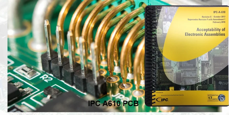
- IPC-A-610 (Acceptability of Electronic Assemblies): The most widely used IPC standard in the electronics manufacturing industry. It sets visual acceptance benchmarks for soldered electronic assemblies, defining precise solder fillet dimensions (toe, heel, and side fillets), component positioning tolerances, solder bridging, and solder balling criteria.
- J-STD-001 (Requirements for Soldered Electrical and Electronic Assemblies): While IPC-A-610 is an inspection document, J-STD-001 is a process standard. It specifies manufacturing methods, flux types, solder alloy purities, cleaning chemistry requirements, and process controls needed to produce reliable solder connections.
- IPC/WHMA-A-620: Requirements and acceptance for cable and wire harness assemblies, covering crimping, soldering, and wire bundling.
- IPC-7711/7721: Rework, modification, and repair of electronic assemblies and printed boards, detailing approved techniques for trace repair, pad replacement, and BGA re-balling.
Complete IPC Standards Reference Matrix
| Manufacturing Discipline | Primary IPC Standard | Companion Standard | Key Engineering Focus |
|---|---|---|---|
| Schematic & Layout | IPC-2221 | IPC-2222, IPC-7351 | Creepage/clearance, conductor width vs current, footprint geometry |
| Material Selection | IPC-4101 | IPC-4204, IPC-4562 | Base laminates, resin systems, $T_g$/$T_d$, copper foil weights |
| Bare Board Fabrication | IPC-6012 | IPC-6011, IPC-6013 | Copper plating thickness, hole wall integrity, dimensional tolerances |
| Bare Board QC | IPC-A-600 | IPC-TM-650 | Visual defect acceptance, solder mask registration, delamination |
| Soldering Process | J-STD-001 | IPC-J-STD-004/005 | Solder alloys, flux chemistry, intermetallic growth, cleanliness |
| PCBA Quality Release | IPC-A-610 | IPC-9261 | SMT/THT joint inspection, component alignment, cleaning residue |
| Handling & Storage | IPC-1601 | J-STD-033 | Baking cycles, moisture barrier bags (MBB), ESD protection |
| Rework & Modification | IPC-7711/7721 | IPC-A-610 | Lifted pad repair, barrel re-plating, jumper wire installation |
Frequently Asked Questions (FAQ)
What is IPC in electronics?
In electronics, IPC (Association Connecting Electronics Industries) is the primary international standards body that develops unified standards for printed circuit board design, base laminate specification, PCB fabrication, and electronic surface-mount assembly inspection.
What does IPC stand for?
IPC originally stood for the Institute for Printed Circuits upon its founding in 1957. Today, it is officially known simply as IPC, with the subtitle "Association Connecting Electronics Industries".
What is the difference between IPC-A-600 and IPC-A-610?
IPC-A-600 is the visual acceptance standard for bare, unpopulated printed boards (inspecting copper etching, drilling, laminate defects, and solder mask). In contrast, IPC-A-610 is the acceptance standard for assembled electronic boards (PCBA), evaluating component mounting, solder joint quality, and soldering defects.
What is the main difference between IPC Class 2 and Class 3?
IPC Class 2 is intended for dedicated service commercial and industrial electronics where high reliability is required, but momentary downtime is not catastrophic. IPC Class 3 is designed for mission-critical, harsh-environment electronics (aerospace, defense, medical life support) where equipment must operate without interruption, requiring thicker plated copper (25 µm), zero annular ring breakout, and 100% inspection.
HILPCB IPC-Certified Manufacturing and Quality Assurance
At HILPCB, all PCB manufacturing processes and turnkey PCBA services comply strictly with certified IPC standards:
- IPC-6012 Class 2 and Class 3 Capabilities: Validated multilayer lamination, high-density interconnect (HDI) microvias, and automated cross-section microsectioning.
- IPC-A-610 Certified Operators: Certified IPC trainers (CIT) and application specialists (CIS) oversee every SMT pick-and-place, reflow, and selective soldering stage.
- Advanced Inspection Verification: 100% flying probe electrical testing, automated optical inspection (AOI), 3D solder paste inspection (SPI), and 3D X-ray inspection (AXI) calibrated to IPC Class 3 limits.
Submit your engineering Gerber files and BOM to HILPCB today to receive an immediate DFM compliance review against applicable IPC Class 2 or Class 3 standards.