

The MIDI (Musical Instrument Digital Interface) keyboard remains the essential interface between musicians and digital audio systems, translating physical expression into precise digital data. At the heart of every professional MIDI keyboard lies a sophisticated PCB that must capture the subtlest nuances of performance—velocity, aftertouch, pitch bend—while maintaining the timing accuracy that musicians demand.
HILPCB provides professional PCB fabrication and PCBA assembly services for music equipment manufacturers worldwide, delivering the precision manufacturing that MIDI keyboard applications require.
Menu Navigation
- High-Resolution Velocity Sensing for Expressive Performance
- USB-MIDI and Communication Interface Implementation
- Audio Output Stage Design for Keyboards with Sound Generation
- Processing Architecture and System Integration
- Controlled Impedance PCB Manufacturing for MIDI Applications
High-Resolution Velocity Sensing for Expressive Performance
Capturing musical expression requires precise sensing of key movement. The difference between a professional keyboard and a toy often comes down to velocity sensing quality—how accurately the PCB measures strike dynamics across all keys.
MIDI Keyboard PCBs demand tight manufacturing tolerances, consistent impedance control, and reliable solder joints to ensure velocity sensing circuits perform as designed across every unit produced.
Key Velocity Sensing Techniques
- Dual-Contact Time Measurement: Two switch contacts at different key travel positions measure hammer velocity through time-difference calculation, achieving smooth 127-step velocity curves with ≤10µs timer resolution.
- FSR Pressure Sensing Integration: Force-Sensitive Resistors enable continuous velocity and aftertouch data, with optimized voltage divider circuits and 12-bit ADC sampling for nuanced expression.
- Optical Sensor Implementation: Contactless measurement using IR LED/phototransistor pairs provides excellent longevity and consistent response, ideal for premium instruments.
- Matrix Scanning Optimization: 8×11 or 9×10 matrices cover 88 keys efficiently, with anti-ghosting diodes and 2kHz+ scan rates capturing the fastest passages accurately.
- Per-Key Calibration Systems: Factory and user calibration with temperature compensation ensures consistent response across all keys, stored in non-volatile memory.
- Aftertouch Processing: Both channel aftertouch (single sensor) and polyphonic aftertouch (per-key FSR) implementations with MPE protocol support.
Manufacturing Requirements for Velocity Sensing
Velocity sensing circuits require precise PCB fabrication with controlled impedance traces for ADC signals, consistent copper weight for stable reference voltages, and reliable via connections for matrix scanning. Fine-pitch multiplexer ICs and ADC components demand accurate SMT placement with AOI verification.
USB-MIDI and Communication Interface Implementation
Modern MIDI keyboards must communicate reliably with computers, tablets, hardware synthesizers, and stage equipment. USB-MIDI implementation requires proper impedance control on differential pairs and precise component placement for reliable enumeration across all host platforms.
The PCB fabrication quality directly impacts USB signal integrity—impedance variations cause communication failures that frustrate musicians and increase warranty returns.
Communication Protocol Implementation
- USB-MIDI Class Compliance: Driver-free operation on Windows, macOS, Linux, iOS, and Android through proper Audio/MIDI class descriptors with optimized endpoint configuration.
- Multi-Port Virtual MIDI: Multiple MIDI ports over single USB connection organize keyboard zones, control data, and system messages for complex routing scenarios.
- Traditional 5-Pin DIN MIDI: Current-loop design with 6N138 opto-isolation prevents ground loops, with proper buffering for MIDI Thru daisy-chaining.
- Bluetooth LE-MIDI: BLE-MIDI standard implementation with 7.5ms connection intervals for acceptable wireless latency, plus intelligent power management for battery operation.
- Low-Latency USB Stack: Optimized firmware ensures <1ms contribution to total system latency, critical for real-time performance feel.
- Running Status Optimization: MIDI message optimization reduces data volume while maintaining timing accuracy for dense note passages.
PCB Requirements for USB Implementation
USB 2.0 requires 90Ω differential impedance with ±10% tolerance. Controlled impedance fabrication maintains signal integrity across production runs, while proper layer stack-up provides adequate ground reference.
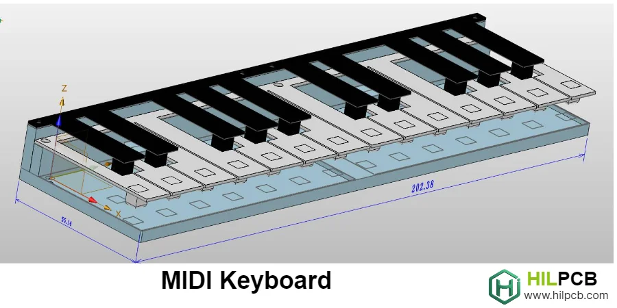
Audio Output Stage Design for Keyboards with Sound Generation
Many MIDI keyboards include onboard sound generation, requiring audio output stages that preserve sound quality while driving studio equipment. Audio PCB performance depends heavily on fabrication quality—noise, crosstalk, and distortion often originate from manufacturing issues rather than circuit design.
Clean power planes, proper ground separation, and consistent dielectric properties are essential for achieving professional audio specifications.
Audio Circuit Design Elements
- High-Resolution DAC Implementation: 24-bit/96kHz+ converters (PCM5102A, AK4490, ES9038) with proper I2S routing, low-jitter clocking, and optimized power supply filtering.
- Low-Noise Analog Stages: Premium op-amps (OPA1612, NE5532) in I-V conversion and output buffering, achieving >100dB SNR and <0.01% THD.
- Balanced Output Drivers: Differential drivers (THAT1646, DRV134) for XLR connections eliminate ground loop hum in professional installations.
- Headphone Amplifier Design: Dedicated headphone stages (TPA6120A2, NJM4556A) provide adequate power for 16Ω-600Ω loads with <1Ω output impedance.
- Ground Plane Strategy: Careful analog/digital separation with single-point connection at DAC prevents digital noise from contaminating audio signals.
- Power Supply Isolation: Separate regulators for DAC and analog stages, with ferrite bead isolation and multi-stage filtering for ultra-low noise.
Audio PCB Fabrication Standards
Audio applications benefit from multi-layer PCB construction with dedicated power and ground planes. Proper copper weight distribution, ENIG surface finish for reliable audio connector soldering, and thorough post-assembly cleaning ensure the low noise floor professional audio demands.
Processing Architecture and System Integration
MIDI keyboard electronics encompass multiple subsystems working together—key scanning, MIDI processing, sound generation, and user interface. Multi-board keyboard systems require reliable inter-board connections and consistent manufacturing quality across all PCBs.
Proper panelization, assembly sequence planning, and functional testing ensure complete keyboard systems work correctly from first power-on.
System Architecture Approaches
- Dedicated MIDI Controller ICs: Purpose-built chips optimize key scanning with built-in velocity curves, reducing firmware complexity for straightforward implementations.
- ARM Cortex-M Series MCUs: STM32F4/H7 families provide excellent performance with hardware timers for precise scanning, USB peripherals, and DMA for efficient data handling.
- FPGA Implementation: Parallel processing enables premium instruments with polyphonic aftertouch, high-resolution scanning, and custom algorithms.
- Multi-Board Architecture: Separating keybed scanner, main processor, and audio output into dedicated PCBs improves manufacturing yield and field serviceability.
- Power Supply Design: USB bus power management for controllers, isolated low-noise supplies for keyboards with audio, with proper inrush limiting.
- Inter-Board Communication: High-speed SPI or parallel buses for keybed data, I2S for audio, with controlled impedance routing.
Manufacturing Considerations
Multi-board keyboard systems benefit from unified quality control across all boards. Panel optimization reduces per-board costs while maintaining dimensional accuracy for mechanical fit.
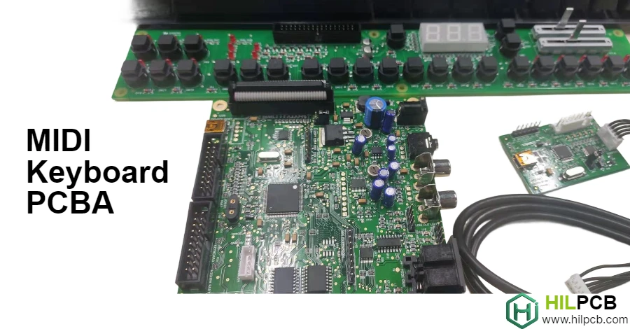
Controlled Impedance PCB Manufacturing for MIDI Applications
USB-MIDI keyboards require controlled impedance fabrication for reliable communication across all host devices. HILPCB maintains 90Ω differential impedance within ±5% tolerance, validated with TDR-measured edge coupons on every production panel.
Why Choose HILPCB for MIDI Keyboard PCB
Impedance-Critical Fabrication
Our multilayer PCB production maintains layer-to-layer registration within ±15-25μm, ensuring consistent impedance across USB differential pairs. Stackup simulation correlates with measured coupon data, providing confidence your USB-MIDI interface will enumerate reliably.
Precision SMT for Audio Circuits
Fine-pitch DAC and audio IC placement demands accuracy—down to 01005 passives and 0.3mm pitch components. SMT assembly with AOI coverage detects placement shift, tombstoning, and solder bridges before boards ship.
Mixed-Technology for Connectors
MIDI keyboards combine SMT electronics with through-hole MIDI DIN connectors and audio jacks. Selective soldering provides robust joints on through-hole components while protecting SMT assemblies.
Prototype Through Production
- Small batch assembly with engineering DFM review
- Turnkey assembly handling component sourcing
- Volume scaling with consistent process control
Contact us with your Gerbers, BOM, and assembly files for DFM feedback and a clear quote.
Common Questions
Why is impedance control important on a MIDI keyboard PCB?
USB-MIDI communication depends on differential signaling that has to stay within a controlled impedance window to enumerate reliably across host devices. If the stackup and routing are not managed carefully, communication problems can appear even when the rest of the board seems functional.
What makes MIDI keyboard assembly different from a simple digital board?
MIDI keyboard designs often combine audio circuitry, fine-pitch SMT devices, and mechanically stressed through-hole connectors in one product. That mix requires attention to both signal integrity and assembly method, rather than treating the board as a generic low-complexity digital design.
What should be validated before a MIDI keyboard PCB is released to production?
Teams should validate USB impedance performance, SMT quality on audio-related devices, connector solder robustness, and overall system integration before release. Production becomes more predictable when communication reliability and audio-supporting hardware have both been verified.