
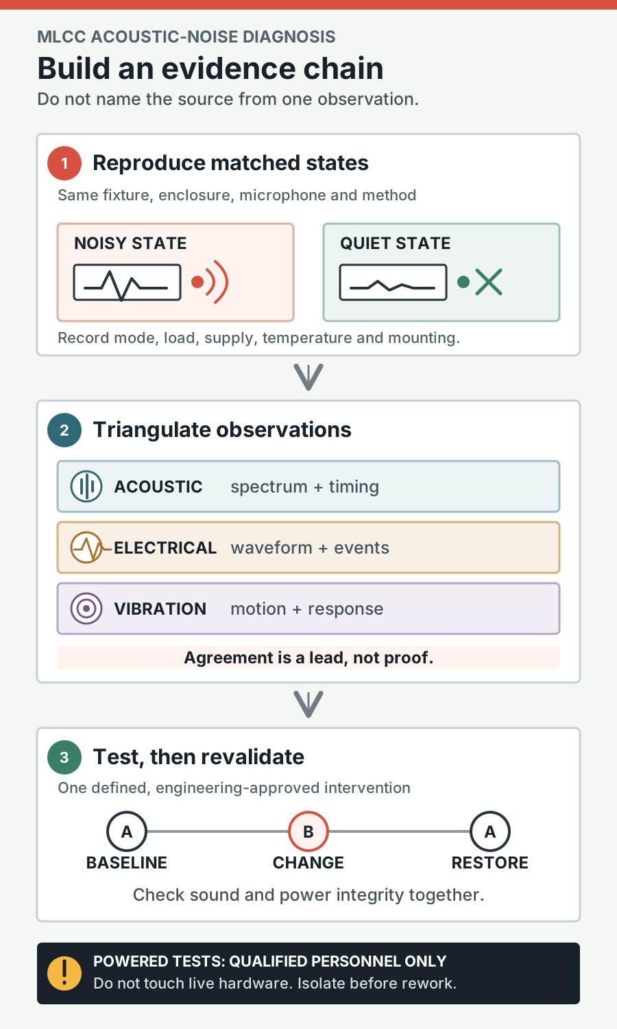
Start by reproducing the sound in a defined operating state, not by replacing the nearest capacitor. Record the noisy and quiet states under the same acoustic and mechanical setup, investigate inductors and other possible sources, and use an engineering-approved intervention to test the leading hypothesis. A matching frequency or a vibration hotspot is useful evidence, but neither proves that an MLCC is the source.
If a controlled change reduces the sound, revalidate the power network, regulator and assembly across the intended operating conditions before accepting it.
First, separate three different phenomena
An audible whine, electrical noise and microphonics can coexist, but they describe different observations and call for different tests.
- Audible acoustic noise is sound radiated into the air. In a singing-capacitor case, a changing electric field deforms a susceptible ceramic dielectric. The mounted capacitor transfers force through its terminations and solder joints into the PCB. The board, its supports and the enclosure can then vibrate and radiate sound.
- Electrical noise is unwanted voltage or current variation. A rail waveform can excite mechanical vibration, but an electrical ripple measurement is not itself an acoustic measurement.
- Mechanical microphonics is the reverse concern: mechanical disturbance produces an electrical response that may appear in a circuit. A test for an electrically microphonic signal does not, by itself, prove which part is producing an audible whine.
Piezoelectricity and electrostriction are related electromechanical mechanisms. Piezoelectric strain has a field-linear contribution; electrostrictive strain has a nonlinear field dependence. Bias and waveform influence the observed response, including fundamental and harmonic components. A real ceramic’s behavior should not be reduced to a single simplified formula. Ko and colleagues examined these contributions under stated test conditions in their research on MLCC electromechanical material properties.
Not every ceramic capacitor sings, and hearing a whine does not establish that a component is damaged. Murata's ceramic capacitor acoustic-noise FAQ describes the ordinary phenomenon separately from a reliability failure.
Make the operating state the first diagnostic decision
A product may be quiet under a steady load and audible during standby, charging, a pulsed load or a regulator’s burst mode. The state can alter the electrical excitation, the mechanical response, or both. In its article on MLCC squealing in laptop battery lines, Murata compared sound and voltage spectra across operating modes in one product. The measured reduction applies to that assembly and test.
Before changing hardware, define at least one repeatable noisy state and, if possible, one quiet comparison state. Record:
- Assembly and firmware revisions, component identifiers and any previous rework.
- Supply voltage, load, temperature, operating mode and the sequence used to reach it.
- Whether the product is open or enclosed, how it is mounted and what supports or cables contact it.
- Microphone position, distance and orientation, background conditions, recording duration, measurement bandwidth or weighting, calibration status and relevant uncertainty.
- The audible character: continuous tone, intermittent chirp, changing pitch or state-dependent pattern.
Keep the fixture, enclosure and microphone arrangement matched between comparisons. A board held differently can have a different mechanical response even when its electrical waveform is unchanged. A phone recording may help preserve a symptom and its timing, but it is not automatically a calibrated sound-pressure measurement.
Capture more than a single peak. A spectrum, time history and operating-state log can show whether sound begins with a load cycle, follows a control event or persists in several modes. Compare levels only with the measurement method and background documented. Project-specific acceptance criteria must be agreed separately; there is no universal pass/fail dB value.
Use evidence to rank suspects, then test causality
The PCB may act as a sounding surface even when the exciter is a small component. Inductors and transformers can vibrate, as can mechanical parts, mounts, covers and other structures. More than one source may be active.
For powered measurements or controlled excitation, trained personnel should follow the applicable electrical safety procedures. Check instrument and probe ratings, grounding, common-mode limits and the intended measurement points before connection. Do not touch a live assembly to locate or damp a sound.
| Symptom or observation | Controlled test | Evidence to look for—and its limit |
|---|---|---|
| Whine occurs only in idle or charging | Reproduce noisy and quiet states with the same enclosure, fixture and acoustic setup; record the state transitions | A repeatable state relationship narrows the search to excitation or mechanics that change with that state. It does not identify a component. |
| Acoustic tone aligns with a rail-voltage feature | Compare sound and relevant electrical waveforms in both states using approved measurement methods | Frequency and timing agreement support a coupling hypothesis. A shared control cycle may also drive an inductor or another structure. |
| Strong motion appears near an MLCC | Map operating vibration where suitable equipment and qualified personnel are available; compare with nearby magnetics and board regions | The moving area may be the exciter, a transmission path or a board resonance. A hotspot alone is not proof. |
| Sound changes with the enclosure or mounting configuration | Compare approved configurations while holding operating conditions and acoustic setup consistent | A repeatable difference implicates the mechanical path or radiation, but does not by itself identify the electrical source. |
| A capacitor remains the leading suspect | Make an engineering-approved, controlled change to the candidate part or its excitation; repeat baseline and changed-state measurements | A consistent reduction tied to the intervention strengthens causality. Check for confounders, other contributors and electrical side effects. |
| Audible sound is absent but a circuit is sensitive to vibration | Under an approved procedure, apply a controlled mechanical stimulus and measure the electrical response | An electrical response is evidence of microphonic sensitivity under that test, not proof of an airborne acoustic source. |
Where available, operating-deflection measurements such as scanning laser vibrometry can help show how a board moves. Polytec illustrates this approach in its article, “How singing capacitors affect the audio experience in consumer electronics.” A moving spot may be part of the transmission path rather than the source.
Electrical-to-vibration coherence or a controlled excitation experiment can provide further evidence when planned by qualified engineers. A common frequency can propagate through the electrical network and mechanical structure, so correlation alone is not conclusive.
Design the intervention before changing the assembly
A useful intervention changes a defined factor and predicts what should happen if the hypothesis is correct. For example, an approved substitute at a suspect location might be expected to reduce a particular tone in the same operating state. A controlled operating-mode change might instead test whether the excitation is necessary for that tone.
Before any part replacement or rework:
- Obtain engineering approval for the change and the test plan. A decoupling capacitor must never be removed as an unreviewed listening test; it may be necessary for rail performance or stability.
- Isolate all applicable supply, battery and stored-energy paths, discharge stored energy, and verify voltage at the relevant test points using the approved procedure. Residual voltage below a hazardous level can still damage components. Apply the required ESD and rework controls.
- Document the original configuration, the exact change and any unavoidable differences in soldering, mounting or routing.
- Measure the changed assembly in the same noisy and comparison states, using the matched acoustic and mechanical setup.
- Where feasible and approved, restore the baseline and repeat the measurement. A baseline–change–restore sequence helps distinguish the intervention from drift or an incidental handling effect.
A quieter result after substitution is stronger evidence when the operating state and relevant electrical waveforms remain comparable. If the rail waveform also changes, the outcome may reflect a changed excitation as well as a changed mechanical response. Neither interpretation should be assumed without further measurement.
If the tone remains, reconsider competing sources and coupling paths. If it decreases but does not disappear, multiple components or mechanisms may contribute. Keep the baseline and changed-condition data even when an intervention fails: they help prevent the team from repeatedly testing the same hypothesis.
Choose a mitigation by its system tradeoffs
A diagnosis may point toward the drive waveform, the capacitor, the mechanical path or a combination. Review proposed changes with engineering and check their effects on electrical performance, ratings, fit and reliability as well as sound.
Change the excitation
Regulator mode, burst behavior, load sequencing or voltage slew may change the force driving the structure. Evaluate the acoustic result across all relevant operating states, not only the original worst case. Also check transient response, stability, efficiency and temperature.
A switching frequency above the audible range does not guarantee silence: an audible-rate operating cycle or modulation envelope may still excite the assembly. Conversely, lowering an audible component of the waveform must not come at the cost of unacceptable rail behavior.
Change the capacitor or network
A lower-strain dielectric, an alternative termination or interposer construction, or a different capacitor technology may be worth evaluating. Texas Instruments discusses several of these approaches in its power-application article SSZTB09; its component comparisons are examples, not universal rankings.
Compare the actual effective capacitance at operating DC bias, temperature and relevant AC conditions—not just the nominal label. The guide to MLCC DC bias and effective capacitance explains how to assess data for the exact part. Review tolerance, aging, voltage and ripple ratings, impedance versus frequency, ESR, ESL and mounted parasitics. Check footprint, height, polarity where applicable, solder process, thermal limits and availability.
A polymer or film candidate can have different high-frequency behavior and may require a coordinated bypass network. A physically larger or differently mounted part can also change assembly stress and reliability. No substitute should be accepted solely because it sounds quieter.
Change the mechanical path or enclosure
Location, board support, thickness, mounting and enclosure contact can alter how vibration is transmitted and radiated. Damping or compliant mounting may help in a particular design, but can also shift a resonance, constrain heat removal, affect serviceability or introduce material and stress concerns.
Opposite-side arrangements and board features require the same case-specific assessment. There is no universally correct orientation, placement or slot geometry, and no guaranteed acoustic improvement. Test the proposed configuration with representative mounting and enclosure boundary conditions.
Revalidate the electrical and acoustic result together
The final comparison should cover both the original symptom and the conditions that could expose a new problem. Use the agreed acoustic method to repeat the noisy and quiet states, then check the changed design over the relevant supply, load, temperature and operating-mode range.
At minimum, the engineering review should address:
- Effective capacitance at bias and the installed network’s impedance, including mounting effects and possible anti-resonance.
- Rail ripple and load-transient response.
- Regulator stability under the intended operating conditions.
- Voltage, current, ripple, thermal and other applicable part ratings.
- Package fit, solderability, assembly stress and reliability.
- Acoustic behavior with the intended board supports and enclosure.
A quieter assembly is not an acceptable fix if it creates an unstable rail or an unreliable construction. Likewise, a change that works only on an open board may not solve the enclosed-product symptom. For background on the network being revalidated, see decoupling network basics and the power integrity checklist.
Engineering handoff checklist
- Identify the assembly, revision, suspected locations and exact part numbers.
- Describe the noisy and quiet operating states and how to reproduce them.
- Record supply, load, temperature, firmware, mounting and enclosure conditions.
- Attach acoustic records with microphone distance, orientation, setup, calibration status, uncertainty, background and measurement settings.
- Include relevant electrical and vibration measurements, with their safety and method limitations.
- List competing sources considered and distinguish observations from conclusions.
- Document each approved intervention, rework controls and baseline–change–restore results where available.
- Record capacitance-at-bias, impedance, ripple, transient and stability evaluations.
- Record ratings, package, assembly and reliability reviews, plus outstanding risks.
- State the project-specific acceptance criteria, owner and required revalidation coverage.
For an assembly discussion or quotation, provide the relevant documentation through the quote request.
FAQ
Does a singing MLCC mean it is failing?
No. Audible vibration alone is not evidence of damage or impending failure. Investigate any separate signs of excessive board strain, unsuitable rework, overheating or other reliability concerns on their own merits.
Can a matching acoustic and electrical frequency identify the capacitor?
It is a useful lead, not proof. The same operating cycle can excite several components or structures. Compare repeatable states and use an approved controlled intervention to strengthen the causal case.
Should I press components to find the sound?
Do not touch a live assembly. Use approved measurements and controlled changes instead. Even a change in sound caused by a mechanical boundary change would not, by itself, prove which component supplies the excitation.
Is replacing the MLCC with a quieter part enough?
Only if the replacement is approved and the complete result is revalidated. Effective capacitance at bias, rail impedance, ripple, transients, stability, ratings, package and reliability all matter alongside sound.
Can moving the board or changing the enclosure eliminate the whine?
It may reduce, shift or amplify a resonance in a particular assembly. Validate the change with representative supports and enclosure conditions, and check electrical performance, thermal behavior and mechanical reliability before release.