
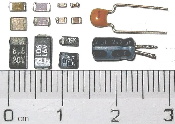
Before releasing a PCB design or approving an MLCC substitute, compare the circuit’s capacitance requirement with evidence for the exact part at its actual operating conditions. A nominal capacitance and voltage rating are starting points, not proof that the capacitor supplies enough capacitance on the powered rail.
The release record should identify the manufacturer’s data, its conditions and limitations, the applicable circuit requirement, and any measurements used to close the gap. If the available curve is typical rather than guaranteed, say so. If the evidence is insufficient, hold the design or substitute for further review rather than converting an estimate into an approval.
Separate the three values
An MLCC selection often starts with three numbers that answer different questions:
- Nominal capacitance is the labeled value under the manufacturer’s specified measurement conditions.
- Capacitance tolerance defines an allowed range around that nominal value under those conditions. It is not automatically a bound on capacitance during operation.
- Rated voltage is a voltage limit specified by the manufacturer. Operating below it does not mean the capacitor retains its nominal capacitance.
The value the circuit needs is effective capacitance at its working point. For a high-dielectric-constant MLCC, that value can change with DC voltage, AC signal level, temperature, frequency, and time-dependent aging. Conditions may interact; they should not be treated as independent correction factors unless the underlying data and method justify doing so.
Murata’s The voltage characteristics of electrostatic capacitance describes changes associated with both DC and AC voltage and recommends considering actual operating conditions. Its examples illustrate the devices shown, not loss percentages for every MLCC.
Establish the circuit requirement first
A curve cannot answer whether a design is acceptable until the engineering team states what “acceptable” means.
For each relevant capacitor or network, document:
- Circuit function: local decoupling, regulator input or output capacitance, bulk energy storage, filtering, or another role.
- Acceptance criterion: for example, minimum effective capacitance at a specified point, a regulator’s stability requirement, a transient voltage limit, or a frequency-dependent impedance target.
- Operating envelope: normal and maximum capacitor-terminal DC voltage, ripple and transient voltage, temperature, relevant frequencies, and service-life assumptions.
- Network context: capacitor quantities, placement, connections, and the effects of traces, vias, mounting, and other components.
Use the voltage across the capacitor, including the relevant tolerance and transient conditions, rather than relying only on the rail’s label. Check the manufacturer’s voltage-rating rules separately from the capacitance calculation.
A capacitance threshold alone may not establish regulator stability or acceptable high-frequency decoupling. The network’s impedance, parasitics, and layout can matter as well. For the wider network context, see decoupling network basics.
Lock the part identity
Record the manufacturer and complete manufacturer part number, including any orderable suffix needed to identify the supplied item. Also record the nominal capacitance, tolerance, dielectric, case size, rated voltage, and any variant or packaging details relevant to procurement.
Do not substitute a nearby search result because it shares a series name or most of an MPN. Similar-looking parts may have different electrical characteristics. Likewise, X5R and X7R describe temperature-characteristic classes; neither label establishes which particular part will retain more capacitance under DC bias.
When a design uses an 0201 passive, check its size naming system, footprint, and assembly requirements as well as its electrical evidence. The 0201 passive assembly release checklist covers those manufacturing checks; it does not establish the capacitance of a particular MLCC under bias.
A part-specific reference, not a bias result
The 2016 Murata GRM188R61C225KE15 reference specification is a useful example of identity control, not a current approval sheet or guaranteed DC-bias dataset. It identifies the GRM188R61C225KE15 part family as a 0603 X5R MLCC with a nominal capacitance of 2.2 µF, a ±10% capacitance tolerance, and a 16 VDC rating. The reference sheet uses a final placeholder for the packaging code, so the ordering record should identify the applicable complete orderable MPN rather than silently dropping that suffix.
The reference specification also gives nominal capacitance test conditions. For this listed part, its table calls for a 1 kHz measurement and a 0.5 Vrms AC measurement level, with specified tolerances, at room temperature. Those are reference-specification measurement conditions, not evidence of capacitance at a chosen rail bias.
The document says its catalog specifications are subject to change and directs users to consult the approval sheet before ordering. Obtain the applicable current approval documentation for a real release. No DC-bias curve point or guaranteed operating minimum for this part is established here.
Read the curve as a controlled piece of evidence
For each proposed part, capture the manufacturer’s data for the exact identity and the conditions relevant to the design. A useful curve record includes:
| Item | What the reviewer must establish |
|---|---|
| Identity | Manufacturer, exact MPN or documented applicable variant, and curve or dataset title |
| Source control | Document number, revision or version, publication or access date, and retained export or record |
| Horizontal axis | Whether bias is in volts or another unit, and the point or range being evaluated |
| Vertical axis | Capacitance in farads, percentage of a reference, or percentage change from a reference |
| Normalization | The baseline used for a percentage: nominal value, initial measured value, or another stated reference |
| Measurement conditions | DC bias, AC signal level and units, frequency, and temperature |
| History | Aging time, heat treatment, and other conditioning, if stated |
| Value status | Whether the data is typical, a specified limit, or otherwise qualified |
A curve labeled “capacitance change” is not necessarily the same as one labeled “capacitance remaining.” For example, a change of −30% from a stated baseline corresponds to 70% of that baseline, not necessarily 70% of the nominal capacitance. Verify the axes and normalization before doing arithmetic.
Record missing conditions as unknown. Do not fill them in from a different graph or assume that a plotted line is a guaranteed minimum. If the curve only covers part of the operating envelope, request appropriate data or define additional validation rather than extrapolating without support.
The Murata DC-bias FAQ illustrates why axis identity matters: its example describes the vertical axis as capacitance change relative to an initial value. That description applies to its example, not automatically to every manufacturer plot.
Compare evidence with the requirement
At each relevant working point, convert the applicable data into the same units and basis as the circuit requirement. Record whether the result is:
- A manufacturer-guaranteed limit under conditions that actually match the requirement.
- A typical-data estimate useful for design assessment but not a guaranteed lower bound.
- A measurement result for identified samples under a documented method.
- An unsupported assumption used only to explore a design.
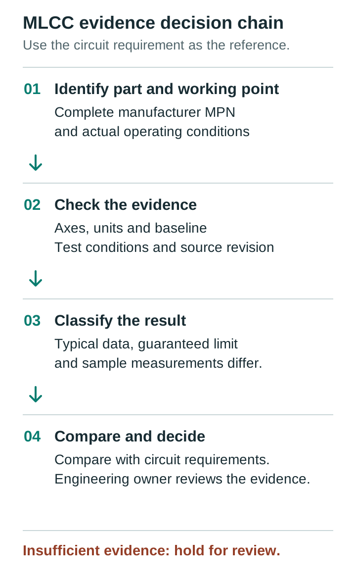
These categories are not interchangeable. A typical curve can guide part selection and motivate margin and testing, but it does not establish the worst part from every production lot. A measured sample can support a release decision within an agreed validation plan, but it does not by itself turn a typical curve into a manufacturer guarantee.
Hypothetical calculation
Suppose a circuit requirement calls for at least 4.0 µF effective capacitance at a defined operating point. An engineer is considering four parallel capacitors, each labeled 2.2 µF.
For illustration only, assume each capacitor contributes 1.1 µF effective capacitance at that point, and assume their capacitances can be added for this particular low-frequency requirement:
On those assumptions, the calculated total is 0.4 µF, or 10%, above the stated 4.0 µF threshold.
This is not manufacturer data, a measured curve point, or a guaranteed worst case. The assumed 1.1 µF is not a claim about the Murata example or any other part. The arithmetic also does not prove acceptable impedance, regulator stability, or performance across temperature and aging. The team must replace the assumption with applicable evidence and judge whether the resulting margin is sufficient under its release criteria.
Do not multiply nominal tolerance, temperature limits, aging estimates, and a typical bias percentage and label the product a guaranteed minimum unless the manufacturer’s data and the validation method explicitly support that treatment.
Measure when the evidence needs it
For a critical rail, or when manufacturer data does not establish sufficient confidence, define a measurement plan before collecting results:
- Identify samples and history. Record the exact orderable MPN, lot information where available, sample count, soldering or heat exposure, elapsed time after conditioning, and storage history.
- Define the method. Use a capacitance-measurement setup or bias fixture suitable for the applied DC voltage. Record instrument settings, frequency, AC test level, temperature, calibration, fixture compensation, and measurement uncertainty.
- Apply the relevant conditions. Measure at the intended capacitor-terminal bias and at other points needed to cover the agreed operating envelope. Respect equipment and component ratings.
- Evaluate the board where necessary. Check the actual circuit response or network impedance when the requirement depends on the assembled layout, regulator behavior, load transient, or parasitics.
- Compare with the acceptance criterion. Document the observed results, uncertainty, sample and lot limitations, and the rationale for acceptance or further testing.
An in-circuit capacitance reading may include parallel components and other circuit effects; it should not automatically be attributed to one MLCC. Conversely, a component measurement in a fixture does not reproduce all board-level behavior. Use both methods where they answer different parts of the requirement.
Choose sample coverage and any measurement guard band according to product risk and the organization’s validation plan. No finite sample set alone proves a universal guaranteed minimum.
Approving a substitute
A substitute is not equivalent merely because its case size, nominal capacitance, tolerance, dielectric code, and voltage rating match. Compare the original and candidate at the same relevant working points, using data with identifiable axes and test conditions. If their curves use different normalization or measurement settings, resolve those differences before treating the comparison as meaningful.
The review should also cover the candidate’s voltage limits, physical fit, procurement identity, and effects on the complete circuit. If the original was released on measurement evidence rather than a guaranteed capacitance limit, the candidate needs an appropriate evidence plan of its own.
Use the broader PCB component substitution approval process to control the change. A sourcing request is not an engineering approval, and a general article cannot approve a specific replacement.
Once a change is approved, the PCB assembly engineering change order checklist can help record the affected baseline, where the change takes effect, and the disposition of existing stock and work in process.
Release decision matrix
| Evidence and result | Decision | Required next step |
|---|---|---|
| Applicable specified limit meets the requirement under matching conditions | Candidate for release | Complete circuit, voltage, and change-control reviews; retain the evidence |
| Typical data indicates adequate performance, but no matching guaranteed minimum is available | Conditional review | Assess margin and risk; perform and document the validation required by the release plan |
| Measured samples pass the agreed test, with known uncertainty and coverage limitations | Candidate for release | Engineering owner reviews sample scope, remaining risks, and board-level evidence |
| Data identity, normalization, conditions, or revision is unclear | Hold | Obtain traceable manufacturer data or perform an appropriate measurement |
| Evidence shows the requirement is not met | Do not release | Revise the network or select another part and repeat the assessment |
| Substitute lacks an approved same-working-point comparison | Do not substitute | Complete the candidate’s technical and change-control review |
“Candidate for release” is deliberately not automatic approval: the responsible owner must accept the evidence for the product and its use.
Handoff checklist and ownership
The release package should travel with the design revision or substitution request, not remain in an engineer’s browser history.
- Design engineer: State the circuit function, operating envelope, acceptance criteria, and approved PCB/BOM revision.
- Component engineer: Record each manufacturer and complete orderable MPN; retain the applicable specification and curve identity, revision, axes, normalization, conditions, and value status.
- Test or validation owner: Attach the test plan, sample and lot identities, instrument conditions, uncertainty, raw results, and comparison with acceptance criteria.
- Design engineer and validation owner: Record the circuit-level conclusion, residual limitations, and any rationale for using typical data or limited samples.
- Procurement or change-control owner: Link an approved substitute to the exact BOM positions and prevent unreviewed variants from being treated as interchangeable.
- Release authority: Record the decision, approver, date, and any conditions for production or further qualification.
For a manufacturing discussion, use the quote request; keep component-validation and substitution approvals in the project’s controlled engineering record.
FAQ
Does an MLCC’s ±10% tolerance include DC-bias loss?
Not automatically. The tolerance applies under the manufacturer’s specified capacitance test conditions. Effective capacitance under operating bias needs its own applicable evidence.
Is a capacitor acceptable if the rail voltage is below its rating?
Being within the voltage rating is necessary, but it does not establish sufficient effective capacitance. Check both the manufacturer’s voltage limits and the circuit’s performance requirement.
Can I use a typical DC-bias curve as a guaranteed minimum?
No. A typical curve can inform selection and validation, but it is not a guaranteed lower bound unless the manufacturer explicitly specifies it as one under applicable conditions.
Does a matching nominal value make a substitute equivalent?
No. Compare the exact parts at the same working points, then review physical, electrical, circuit-level, and change-control requirements before approving the substitute.
What if the manufacturer’s curve omits the AC test level or aging condition?
Record the condition as unknown and do not assume it matches the application. Obtain clarification or use an agreed measurement and validation plan before making the release decision.