
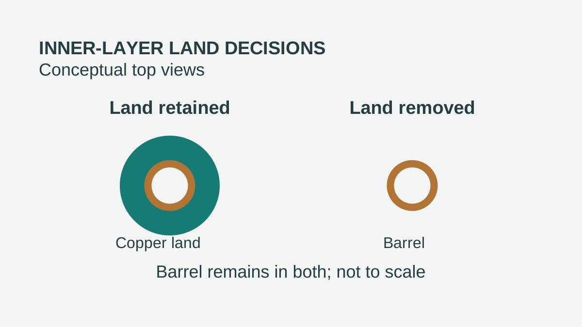
Decide each inner-layer pad’s disposition only after identifying its electrical connections, protected features and applicable release authority. Retaining and removing a non-functional pad are both possible design choices; neither is a universal default for reliability or signal integrity.
Make the decision against a specific design and stackup version. For each hole group and layer, record the existing geometry, clearance, proposed disposition, exceptions, evidence gaps and approvals. If the evidence or authority is unresolved, keep that state visible rather than presenting a CAM edit as an approved design.
A non-functional pad is a copper land around a plated through hole that has no intended electrical connection on that layer. Removing that land does not remove the plated barrel. Removing a barrel stub by backdrilling is a separate operation, with its own design, fabrication and release decisions.
Start with connections and protected features
A pad can appear unconnected in one view while serving a purpose elsewhere in the design package. Before classifying it as a removal candidate, establish the hole’s net, layer span and intended connections from the controlled design data. Check every traversed copper layer, including connections to planes, traces and other features that may be represented differently in different outputs.
Then identify features that the design, drawing, customer agreement or approved exception protects. Examples to investigate include:
- Lands required for intended trace or plane connections.
- Outer-layer lands associated with component, connector or test interfaces.
- Lands covered by a specific mechanical, assembly or reliability instruction.
- Hole groups subject to a customer-defined padstack or controlled exception.
- Features whose purpose is uncertain and needs design-owner clarification.
Do not infer that an unconnected land is protected merely because one of these concerns is possible. Record the actual instruction or mark its status as unknown. Conversely, electrical non-connection alone is not permission to delete copper.
The values and checks in the record below are deliberately illustrative, not annular-ring acceptance criteria. Check any geometry and claimed performance effects against the specific design and applicable requirements.
Make the decision at the right granularity
A useful decision unit is one hole group on one copper layer, tied to a particular stackup and design revision. Holes belong in the same group only when their relevant padstack, connections, construction and review needs are sufficiently alike. Split a group when an individual hole has a different connection, exception or evidence requirement.
For each unit, capture:
- Identity: hole IDs, net or net class, layer span, stackup revision and design revision.
- Function and protection: intended connection, protected feature or documented reason for an exception.
- Geometry: finished-hole and land dimensions, relevant plane opening and other nearby copper; identify unknowns.
- Clearance: the geometry checked, how the value was derived and whether nearby features remain unchecked.
- Disposition: retain, remove, or unresolved—not simply “unused.”
- Evidence: applicable contract and specification revisions, construction details, SI coverage and reliability evidence, including gaps.
- Authority: designer, fabricator and customer review or approval status, as applicable, plus the released file revisions.
A fabricator may identify a useful change, a clearance concern or an inconsistency in the supplied data. That proposal is not automatically an authorized design change. The applicable agreement and design-owner disposition determine how it proceeds.
Hypothetical two-group layer record
In this hypothetical example, the dimensions are chosen to make the arithmetic easy to check. They are not manufacturing limits, tolerances, qualification criteria or recommended pad sizes.
Common record: Design baseline D17; proposed change package D18; conceptual stackup S1. S1 has L1 signal, L2 reference plane, L3 reference plane and L4 signal/ground copper. Both hole groups are through holes spanning L1–L4. D17 depicts lands on all four layers.
Board thickness, material system, copper thickness, hole tolerances, plating details and operating environment are unknown. The governing contract and specification revisions are pending identification. These omissions prevent this example from becoming a fabrication release.
- Group A: H01–H20, signal vias with intended connections on L1 and L4. The group uses an illustrative 0.25 mm finished-hole diameter and 0.50 mm land diameter.
- Group B: H21–H28, ground vias with intended connections on L1, L2 and L4. The group uses an illustrative 0.30 mm finished-hole diameter and 0.60 mm land diameter.
All stated plane openings are concentric, nominal illustrations. Outer-layer clearance to other copper has not been checked.
| Group | Layer | Existing geometry and clearance record | Function or exception | Proposed D18 disposition | Evidence gap |
|---|---|---|---|---|---|
| A | L1 | 0.50 mm land; nearby-copper clearance unknown | Intended signal connection | Retain | Connection and surrounding geometry need release verification |
| A | L2 | 0.50 mm land in 0.80 mm plane opening; nominal land-to-opening edge gap 0.15 mm | No intended connection identified | Remove | SI effect, actual surrounding geometry and construction-specific reliability evidence pending |
| A | L3 | 0.50 mm land in 0.80 mm plane opening; nominal gap 0.15 mm | A design note places this land under review for a possible protected feature | Retain provisionally | Purpose and authority of the note are unknown |
| A | L4 | 0.50 mm land; nearby-copper clearance unknown | Intended signal connection | Retain | Connection and surrounding geometry need release verification |
| B | L1 | 0.60 mm land; nearby-copper clearance unknown | Intended ground connection | Retain | Connection and surrounding geometry need release verification |
| B | L2 | 0.60 mm land connected to the plane | Intended plane connection | Retain | Connection geometry and release interpretation need verification |
| B | L3 | 0.60 mm land in 0.90 mm plane opening; nominal land-to-opening edge gap 0.15 mm | No intended connection identified | Remove | Clearance context and construction-specific reliability evidence pending |
| B | L4 | 0.60 mm land; nearby-copper clearance unknown | Intended ground connection | Retain | Connection and surrounding geometry need release verification |
Approval record for every row: Designer/design owner: pending. Fabricator: pending. Customer: pending; whether customer approval is required for each disposition has not yet been established under the agreement. No D18 row is approved or released.
The proposed removals are candidates, not conclusions. Group A’s L3 land is provisionally retained because its protected status is unresolved, not because retention has been proven superior. If the designer confirms that the note does not apply, the record can be revised and reviewed. If it does apply, record the controlling instruction and any required exception.
Check the simple geometry
For Group A on L2 or L3, assuming concentric circles:
Nominal radial land width = (0.50 mm - 0.25 mm) / 2 = 0.125 mm
Nominal land-to-plane-opening edge gap = (0.80 mm - 0.50 mm) / 2 = 0.15 mm
For Group B on L3:
Nominal radial land width = (0.60 mm - 0.30 mm) / 2 = 0.15 mm
Nominal land-to-plane-opening edge gap = (0.90 mm - 0.60 mm) / 2 = 0.15 mm
These calculations describe the illustrated land before removal. They do not establish minimum annular ring or finished clearance. In particular, the finished-hole diameter is not enough to calculate clearance from the outside of the plated barrel to the surrounding plane after land removal. Barrel geometry, tolerances, registration and other nearby copper still need examination.
Review evidence without turning it into a default
The relevant reliability question is not simply whether a paper found one treatment better. It is whether the tested construction, processing and failure criteria help answer the question for this hole group.
Hunt, Wickham, Birch and Furlong’s 2009 paper directly compared retained and removed non-functional pads in a specific fine-grid PTH construction. The study used a 2.5 mm, 10-layer, high-Tg glass-epoxy board with 10:1 PTHs after six 260°C reflows. Under its respective thermal-cycling and interconnect-stress-test conditions, the pads-out patterns failed later.
That is useful direct evidence, but it is narrow. The methods used different failure criteria, and the authors characterized the pad effect as secondary to factors such as plating quality and material characteristics. Their proposed stress-concentration explanation was a hypothesis. Sample independence, censoring and full hole geometry were not completely disclosed. The study does not establish a universal disposition, product lifetime or acceptance threshold.
When comparing materials for a different construction, carry the specimen and test conditions with each reported value. The PCB material data sheet guide explains how to review those conditions for a stackup.
Smetana and coauthors’ PTH reliability study is relevant construction and test context, but it is not an isolated pad-retention comparison. Its observations involving sections with removed lands also involved differences including hole size and copper volume. Do not attribute those observations solely to pad removal.
For signal integrity, record the model or measurement actually available for the proposed geometry. Via barrel, lands, plane openings, return paths and neighboring structures interact; the effect of changing one land depends on the construction and channel. A model of one layer or one via type does not automatically cover every group. If model coverage is absent, write “not evaluated,” not “no effect.”
For the related interaction between via geometry and the return path, see the via and return-path discussion.
Separate the land decision from backdrilling
An inner-layer land is copper around the plated hole at a particular layer. Removing it leaves the plated through-hole barrel in place. The barrel can still include a stub beyond the layer where a signal exits.
Backdrilling is a separate controlled operation intended to remove a specified portion of that barrel. It requires its own assessment of entry side, depth, remaining stub, clearances, tolerances and affected connections. Approving pad removal does not approve backdrilling, and approving a backdrill does not by itself resolve every land disposition.
If both changes are proposed, link their records so reviewers can assess the combined geometry. Keep each operation’s authorization and released outputs explicit.
Hand off a controlled change, not an assumption
Before fabrication, determine who may alter the padstack in CAM and under what conditions. The answer may be in the purchase agreement, drawing, approved deviation or other controlled instruction. If it is unclear, ask; do not infer blanket authority from a previous order or from a fabricator’s usual process.
A practical release sequence is:
- Identify the baseline. List D17’s native design, fabrication outputs, drill data, stackup, drawing and any other controlling files with revisions.
- Issue the proposed delta. Identify the exact hole IDs and layers affected, including exceptions and the proposed D18 geometry. Preserve the fabricator’s proposal separately from the design-owner decision.
- Resolve open items. Review connections, protected features, geometry, contract requirements, SI coverage and relevant reliability evidence. Obtain the designer, fabricator and customer dispositions required by the agreement; record pending or not-applicable states with their basis.
- Reconcile the manufacturing data. Compare the CAM interpretation with the approved layer-by-layer record: hole locations and spans, plating designation, layer mapping, lands, plane openings, connections and any separately approved backdrill data.
- Release matching files. Identify the authoritative package and revision, and use checksums or another controlled method to identify the files sent and accepted. The drawing, stackup, drill data and layer data must describe the same approved design.
- Close the loop. Retain the review record, approvals, accepted deviations and fabricator confirmation. If a discrepancy remains, stop and resolve it rather than silently substituting one file’s interpretation for another.
A filename match alone is not a geometry check. Nor does a fabricator’s feasibility review necessarily constitute customer acceptance. The design handoff guide covers the broader release package.
For layer mapping, drill data and revision checks in the fabrication package, see Gerber data preparation.
In this example, D18 cannot be released as approved while the listed evidence and approvals remain pending. The parties could instead agree on a different, explicitly documented disposition or hold the affected change for further review. The files delivered for manufacture must match the decision actually authorized.
For multilayer PCB fabrication or a project that also needs PCB assembly, use the quote request and supply the controlled design package and unresolved padstack questions. Confirm the applicable process and review scope for the project directly rather than assuming them.
Is an electrically unconnected inner-layer pad automatically safe to remove?
No. First check for protected features, contractual instructions, geometry concerns and design intent. Record a layer-specific proposal and obtain the approvals required for that change.
Does removing non-functional pads always improve reliability?
No. The Hunt et al. study found later failure for pads-out patterns in its particular tested construction and conditions. That result does not establish the direction or magnitude of an effect for every board.
Does removing a land eliminate a via stub?
No. Land removal leaves the plated barrel in place. Backdrilling can remove a specified barrel portion, but it is a separate operation requiring its own design and authorization.
Can the fabricator change the padstack in CAM without asking?
Only the applicable agreement and controlled instructions can establish that authority. If authority is unknown, resolve it before the change; record the proposal, design-owner disposition and any required customer approval.
What if the released drawing and CAM files disagree?
Hold the affected release and resolve the discrepancy with the responsible parties. Then issue and identify a matching approved package; do not assume that a drawing note or a filename alone has settled the geometry.