
Specify a PCB slot or cutout by its finished shape, dimensions, position and plating status, then agree on tolerances and inspection with the fabricator. The process may involve routing, multiple passes or an agreed drill-and-route method; the drawing and data should describe the required result rather than assume a particular machine.
For plated-hole sizing and a master hole table, see the finished hole size guide. The decisions here concern opening geometry, mating parts, fabrication data and the limits of using a slot for electrical isolation.
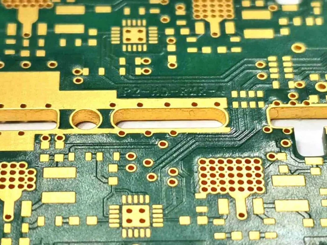
1. Drills, Slots and Cutouts: Use the Same Words as the Fabricator
| Term | Definition | Made by | Typical use |
|---|---|---|---|
| Drilled hole | Round hole from a single plunge | Drill | Vias, component leads, round mounting holes |
| Slot | An elongated opening; specify the end shape | Routing or an agreed drill-and-route method | Blade terminals, power tabs, keying, isolation |
| Cutout | An internal opening, often rectangular or irregular | Fabricator-selected process to meet the contour | Connector bodies, displays, airflow, mechanical clearance |
| Profile (outline) | The board edge | Router, scoring or punching | Board shape, edge notches |
Two further distinctions matter:
- Plated vs non-plated. Identify the required wall finish and any connected copper layers explicitly; agree on process compensation and inspection with the fabricator.
- Component-level vs board-level. A slot can be associated with a component footprint in CAD, while an independent cutout may be defined on a mechanical layer. Check the exported data after changes: the CAD association does not guarantee a manufacturing stage or position accuracy.
2. How Should Slot Size and Position Be Specified?
Define finished width, overall length and end shape, or a complete cutout contour. Give the size tolerance and the position relative to a stated datum, pad, hole or board edge. For a mating feature, provide the mating-part drawing and required fit. Identify plating, connected layers, minimum material webs, copper clearances and critical inspection requirements.
The manufacturing sequence and registration depend on the actual design and process. A routed opening may use more than one pass; neither a file type nor a footprint association guarantees a particular machine, process stage or positional tolerance. Ask the fabricator to confirm the method and achievable tolerances for the stackup.
Example: checking a mechanical fit
Suppose a non-plated opening is specified as 2.00 ± 0.10 mm wide and its mating tab as 1.75 ± 0.05 mm wide. At the dimensional limits, the opening is 1.90 mm and the tab is 1.80 mm, leaving 0.10 mm before location error, end geometry, orientation and assembly variation. This illustration is not a capability claim or fit approval; check the full interface and agree on tolerances and measurement.
3. Design Rules for Slot and Cutout Geometry
Agree the following requirements for the actual board before committing a footprint.
| Feature | Specify or confirm | Why |
|---|---|---|
| Slot width and length | Finished dimensions, tolerance, end shape, plating and board thickness | Feasibility depends on the geometry and process together |
| Inside corner | Allowed radius or relief and the proposed process | A round routing cutter leaves a radius on the cut boundary |
| Slot to slot or hole | Minimum finished material web | Handling and machining depend on the actual geometry; see the hole-to-hole spacing guide |
| Copper to opening edge | Required clearance, layers, nets and position tolerance | Mechanical and electrical requirements both matter |
| Overlapping drill hits | Provide an explicit slot or contour and agree on any drill-and-route method | A row of hits is ambiguous as a slot definition |
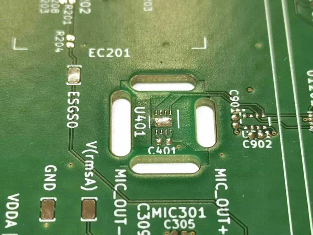
Inside corners and mating parts
A rectangular part such as a connector body, a display or a heatsink tab requires checking the complete opening and corner geometry. Options include:
- Make the cutout larger after checking the mating geometry and tolerances.
- Add corner reliefs, checking their position against nearby copper and mechanical features.
- Agree on a process and allowed corner radius with the fabricator and verify the fit.
4. Plated Slots
Plated slots carry current and solder for blade terminals, power tabs and some connectors.
- Give the finished size and tolerances, and agree on process compensation and measurement.
- Identify connected layers and pads and agree on the required copper land and registration for the design.
- Specify wall requirements and any inspection evidence needed for the application.
- Mark it as plated in the data. Use the plated drill/route file or an explicit attribute; do not rely on CAM inferring plating from copper.
The finished hole size guide shows how to list plated slots in a master hole table with finished width, length and tolerance.
5. Isolation Slots for Creepage
An isolation slot changes the insulating surface geometry between conductors and may affect creepage distance. It does not automatically establish the required creepage distance or electrical clearance. The applicable product standard, its edition, operating conditions and actual geometry govern the assessment.
Give a qualified safety engineer the complete design, including copper and other conductors on both faces, board thickness, slot contour and minimum finished dimensions, component and enclosure geometry, and relevant environmental and voltage conditions. Consider all applicable candidate paths and their shortest valid route under the applicable rules, not just a path around one slot end. Evaluate air clearance separately; a slot alone is not proof of clearance compliance.
Record the standard and edition, conditions, measurement interpretation, required creepage and clearance, and how manufacturing tolerances affect the result. Where a standard treats narrow grooves or slots differently, have the qualified assessor establish how the rule applies to the actual design. Obtain the required product-level verification before treating the feature as compliant.
6. Putting Slots and Cutouts in the Data
| Method | Use for | Watch out for |
|---|---|---|
| Slot command in the drill/route file (Excellon slot or route, with width and end points) | Plated and non-plated slots | Confirm that the exported data represents the intended geometry and is accepted by the receiving CAM system |
| Dedicated mechanical or route layer (Gerber), with closed outlines or paths | Slots and cutouts | State whether lines are the finished cut edge or the cutter centerline; keep them aligned with copper layers |
| Profile layer containing outline and cutouts together | Simple boards | Make every contour closed; mark which closed shapes are cutouts |
| Gerber X2 attributes (profile, plated/non-plated file functions) | Removing ambiguity about file purpose | The receiving CAM must read them; still include a readme or drawing note |
| Copper or legend layer only | Never as the only definition | Easily overlooked; legend may be clipped, copper may be etched |
Separate plated and non-plated slots or use agreed plating attributes, and list each opening's finished shape, size, position, plating and tolerances on the drawing. Inspect the exported files in a viewer and resolve conflicts with the supplier. For a full data release, see our Gerber data preparation guide and the ODB++, Gerber X2 and IPC-2581 comparison.
7. RFQ and Drawing Checklist
- List each opening with finished contour, dimensions, end shape, plating and tolerances.
- Provide the stackup and datums, position requirements and connected layers for plated features.
- Identify mating interfaces, minimum webs, copper clearances and critical inspection evidence.
- Have a qualified safety engineer assess isolation features against the applicable requirements and complete assembly geometry.
- Ask the fabricator to confirm feasibility, accepted data, tolerances and inspection scope for the specific order; resolve exceptions before release.
For edge-plated half holes, see our castellated PCB guide, and for panels with routed tabs and breakaway features, our panelization design guide. When requesting a multilayer PCB or FR-4 PCB quote, include the drawing and drill, route and mechanical data in your quote request, and identify the dimensions and evidence that need agreement.
FAQ
What is the difference between a PCB slot and a cutout?
Slot usually describes an elongated opening; cutout often describes a larger or irregular internal opening. Specify the actual finished shape and plating because the names do not define a manufacturing method or tolerance.
What is the minimum slot width on a PCB?
There is no single value for every design. Ask the fabricator to confirm the finished width, length, board thickness, plating, tolerance and proposed process together for your order.
Can a PCB cutout have square corners?
A round routing cutter leaves a radius on an internal cut boundary. Specify the allowed corner geometry and check whether a larger opening, reliefs or another agreed process satisfies the mating part and surrounding copper requirements.
How wide must a creepage slot be?
The required dimensions depend on the applicable standard and actual design. A qualified safety engineer should assess the minimum finished geometry, all applicable creepage paths and electrical clearance under the correct product standard and conditions.
How should I define slots in Gerber or drill files?
Use a slot command, route path or defined contour accepted by the fabricator. State whether lines represent finished edges or tool paths, identify plating, and check that the exported data agrees with the drawing.