

In electronics prototyping, breadboards and protoboards are two of the most widely used tools for building and testing circuits before committing to a full PCB design. Many beginners assume they are interchangeable, while experienced engineers see them as complementary stages in a structured prototyping workflow. Used correctly, both platforms help reduce design risk, lower costs, and shorten development time.
This guide explains what breadboards and protoboards are, how they work internally, how they differ in electrical and mechanical performance, and how they fit into a modern product development pipeline.
1. What Is a Breadboard and How Is It Used in Prototyping?
A breadboard is a solderless prototyping platform that allows you to build and modify circuits quickly without permanent connections. The name comes from the early days of electronics, when experimenters literally used wooden bread-cutting boards as mounting surfaces for components. Today, the term refers to plastic boards with a matrix of holes and hidden metal contacts underneath.
Breadboards are ideal for:
- Early circuit experiments where the topology may change often
- Education and training, where beginners need a low-risk way to learn wiring and circuit behavior
- Proof-of-concept prototypes that must be assembled and modified quickly
- Low-frequency, low-current circuits where parasitic effects are not critical
Because no soldering is required, components, jump wires, and small modules can be plugged in and removed repeatedly. This makes breadboards extremely cost-effective for labs and makerspaces where many different prototypes are built and torn down.
Key Characteristics of Breadboards
- Solderless connections: Components connect via spring-loaded clips; no tools or soldering skills are needed.
- High reusability: The same board can be used for hundreds of different circuits.
- Beginner-friendly layout: Rows, columns, and power rails are arranged in a standardized pattern that matches DIP IC pin spacing.
- Fast iteration: Changing a component or rerouting a signal is as simple as moving a jumper wire.
Typical Limitations
- Limited to through-hole and DIP-style components unless adapters are used.
- Not suited for RF, very high-speed digital, or high-current power circuits.
- Mechanical connections can become loose over time, causing intermittent faults.
2. What Is a Protoboard (Prototyping Board) and Why Is It Important?
A protoboard—short for prototyping board—is a board used to create permanent or semi-permanent prototypes with soldered connections. Protoboards are sometimes called perfboards, stripboards, or proto PCBs, depending on how the copper pads and traces are arranged.
While breadboards are optimized for flexibility and reuse, protoboards are optimized for:
- Electrical stability
- Mechanical robustness
- Long-term reliability
- Closer behavior to real PCBs
Engineers typically move to a protoboard once a breadboarded circuit is stable and ready for more realistic testing under load, vibration, or extended run-time.
Core Advantages of Protoboards
- Soldered mechanical connections: Components are fixed in place; there is no risk of leads slipping out during use or transport.
- Improved signal integrity: Copper pads and traces provide more predictable impedance and lower parasitics than spring clips and long jumper wires.
- Higher current capability: Wider copper areas and soldered joints support stronger currents than breadboard contacts.
- Better thermal performance: Copper can dissipate heat more effectively than small spring contacts.
- Support for more component types: With suitable layout or adapters, protoboards can accommodate both through-hole and some SMD parts.
When Protoboards Are Typically Used
- After initial functional testing on a breadboard
- When the circuit needs to run for long periods or in harsher environments
- When you need a prototype that can be installed in an enclosure or demo product
- As an intermediate step before designing a dedicated PCB layout
3. Key Differences Between Protoboards and Breadboards
Although both tools are used for prototyping, they serve different roles and have very different electrical and mechanical characteristics. Understanding these differences helps you select the right platform at each stage of the design.
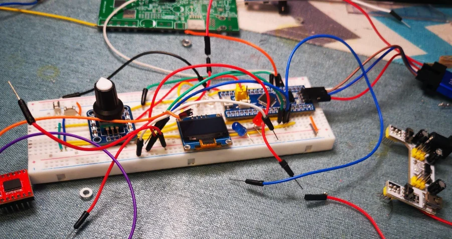
Structural and Electrical Differences
Connection Method
- Breadboard: friction-based spring clips under a plastic hole grid
- Protoboard: soldered copper pads, strips, or semi-custom copper patterns
Reusability
- Breadboard: highly reusable, meant for many temporary circuits
- Protoboard: usually single-use, intended for one design per board
Signal and Power Performance
- Breadboard: prone to parasitic capacitance, resistance, and inductance; not ideal for precision or high-speed signals
- Protoboard: more stable electrical behavior; suitable for higher currents and more demanding analog/digital designs
Mechanical Stability
- Breadboard: components can be dislodged if the board is bumped or transported
- Protoboard: soldered joints lock components in place
Component Compatibility
- Breadboard: best for DIP ICs, headers, and basic through-hole parts
- Protoboard: supports through-hole and, with adapters or careful layout, some SMD components
Summary Comparison Table
| Feature | Breadboard | Protoboard |
|---|---|---|
| Connection type | Solderless spring contacts | Soldered copper pads/traces |
| Typical use | Early testing, education | Final prototype, pre-PCB validation |
| Reusability | High | Low |
| Signal integrity | Low to moderate | Moderate to high |
| Current capability | Low | Higher |
| Mechanical robustness | Moderate | High |
| SMD compatibility | Poor (needs adapters) | Better, with suitable layout |
4. Inside a Breadboard: Structure, Behavior, and Practical Limits
To understand why breadboards behave the way they do, it helps to look at their internal construction and how it affects circuit performance.
Internal Structure of a Breadboard
Plastic socket with perforations
The visible top layer is a plastic block with a grid of holes. These holes are arranged in groups of five for terminal strips and in long lines for power rails.Alloy spring clips (contacts)
Under each group of holes, a metal spring clip made from nickel silver or tin-plated phosphor bronze connects those holes electrically. When you insert a component lead or jumper wire, the spring grabs it and forms a temporary electrical connection.Terminal strips
These strips connect rows of 5 holes, typically used for IC pins, resistors, capacitors, and other discrete components.Bus strips (power rails)
Long horizontal or vertical strips provide distributed power and ground. They are often marked with red and blue/black lines for VCC and GND.Jumper wires
Pre-cut or hand-made wires bridge different parts of the board, linking components, rails, and subcircuits.
Electrical Behavior and Limitations
Contact resistance
Spring contacts introduce variable resistance, especially after many insertions. This can cause voltage drops, noise, or intermittent faults.Parasitic capacitance and inductance
Long jumper wires and parallel metal strips add parasitic elements that distort high-frequency signals and fast edges.Low frequency and current limits
Breadboards generally perform best below about 10 MHz and at relatively low currents. Pushing beyond these limits can result in unstable behavior.Sensitivity to movement
Because connections are friction-based, any physical motion, vibration, or cable tugging can alter contact pressure.
For all these reasons, breadboards are perfect for concept validation and learning, but not for final performance evaluation or deployment.
5. Types of Protoboards and Their Roles in Circuit Development
Protoboards come in several structural variants, each optimized for different wiring styles and levels of complexity. Choosing the right type helps streamline your build and minimize rework.
5.1 Solderless Protoboards
These are less common but exist as an intermediate step between breadboards and fully soldered boards. They may use alternative clip patterns or different hole spacing.
- Reusable like breadboards
- Slightly different routing patterns
- Still not ideal for high-frequency or high-current applications
5.2 Perfboards (Pad-Per-Hole)
Perfboards have a grid of holes, each with an individual copper pad on one side.
- Fully flexible wiring: You decide how everything connects using solder bridges or short wires.
- Ideal for custom one-off designs: Especially useful when the circuit does not map nicely to stripboards or matrix layouts.
- Good for analog circuits: Short point-to-point connections can minimize parasitics.
5.3 Stripboards
Stripboards have parallel copper strips running along rows or columns of holes.
- Fast construction: Single strips can serve as buses for power, ground, or signals.
- Easy modifications: Tracks can be cut with a knife or drill bit to isolate sections or change routing.
- Great for repeated patterns: For example, multiple similar amplifier or logic stages.
5.4 Proto PCBs (Prototype PCBs)
These are semi-custom boards designed to mimic real PCB behavior.
- May include:
- Plated through-holes
- Ground planes
- SMD pads
- Dedicated connectors or bus areas
- Closer to final PCB performance: Excellent for advanced prototypes and small production runs.
- Supports mixed technology: Combining through-hole and surface-mount components in one prototype.
6. How Breadboards and Protoboards Fit Into a Complete Prototyping Workflow
Breadboards and protoboards are not competing solutions; they are complementary tools in a staged development process. Using both correctly can significantly improve design quality and reduce overall development time.
A Typical Prototyping Workflow
Concept & Exploration (Breadboard)
- Quickly wire up ideas and confirm that basic functionality is correct.
- Swap components, experiment with values, and test different topologies.
- Ideal for classroom labs, hobby projects such as ESP32 projects and Raspberry Pi projects, and initial R&D experiments.
Stabilization & Refinement (Protoboard)
- Once the circuit is stable, rebuild it on a protoboard with soldered connections.
- Shorten leads, tighten layout, and improve grounding to see near-final behavior.
- Use this phase to test under realistic loads, higher currents, or longer operating times.
PCB Design & Validation
- Translate the refined protoboard layout into a proper PCB schematic and board layout.
- Optimize trace widths, copper pours, safety clearances, and connectors.
- Fabricate, assemble, and validate the final PCB against specifications.
- A PCB prototype service can turn the first layout into bare boards for this step.
When to Move from Breadboard to Protoboard
Move from breadboard to protoboard when:
- The circuit no longer changes frequently.
- Signal integrity and noise become important.
- You need to run the circuit continuously for hours or days.
- You plan to mount the board in an enclosure or field-test environment.
- You want a prototype that can be replicated or shipped to other team members.
Benefits of Combining Both Platforms
- Reduced design risk: Breadboards catch early logic or connection mistakes.
- Improved performance confidence: Protoboards reveal real-world behavior under load.
- Faster PCB development: You move into CAD tools with a thoroughly vetted circuit.
- Lower total cost: Fewer PCB spins, less rework, and more predictable lab time.