
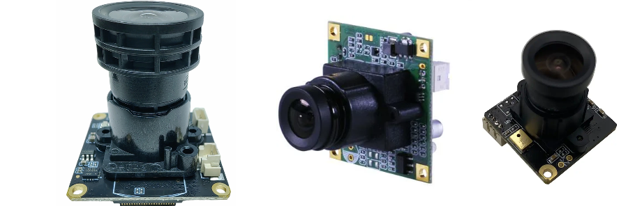
A pan-tilt-zoom camera combines an image sensor and processor with moving optics, motor drives and field wiring. Its PCB must keep the video path working while motors accelerate, power rails change load and the assembly moves through its intended range. Wide-area surveillance, close-up inspection and alarm-directed tracking share this architecture, but their image, motion and environmental requirements differ.
Start with the sensor/processor interface, motor and lens specifications, power source, motion envelope and enclosure. These inputs determine the stackup, driver stage, interconnect and validation plan more directly than a resolution label alone.
Core Design Principles of PTZ Camera PCB: The Foundation of Reliability and Performance
The main design tasks connect three parts of the camera:
- Video signal integrity: Sensor links, memory and Ethernet have different electrical and timing requirements. Preserve the specified channel margin from sensor to processor, and validate the encoded output separately.
- Power integrity: The processor, sensor, pan/tilt drivers, zoom mechanism and optional heater or IR illumination share a finite input-power budget. Check the worst permitted combination of loads and transient rail behavior.
- Electromechanical reliability: The cable or flex must accommodate the actual bend/twist path, and components and connectors need suitable support. Validate motion and environment together with the assembled camera.
High-Speed Signal Integrity: Sensor Links, Memory and Network Paths
Raw sensor traffic and compressed network video are different data streams. Raw payload scales with pixel count, frame rate and bits per pixel; its required line rate also includes interface overhead. Compression settings and scene content determine the recorded bitrate.
Use high-speed PCB methods where the selected interfaces require them:
- Interface-specific routing: CSI-2 is a camera protocol that can use different PHYs. D-PHY differential lanes and C-PHY trios do not share one routing recipe. Use the actual sensor/receiver implementation guidance for lane arrangement, skew and connector/cable limits.
- Impedance control: Agree target impedance and tolerance for each relevant interface with the component guidance and proposed stackup. Do not transfer a generic 90 Ω or 100 Ω value across every bus.
- Via optimization: Evaluate transitions and stubs against the channel budget. Back-drilling or microvias can help a demanding channel, but they add cost and are not mandatory for every camera link.
- Reference planes: Surface microstrip uses a nearby reference plane; stripline is embedded between reference planes. Maintain the intended return path through layer changes and across connectors. Panoramic multi-sensor cameras need the same discipline for each active link.
Threat Protection Layers: From Perimeter to Core
A comprehensive security system employs layered defense. PTZ cameras are typically deployed in the area monitoring and target identification layer, working in interaction with other devices to build a defense-in-depth system.
- Perimeter Layer: Electronic fences or infrared beam devices powered by Fence Detection PCB form the first line of defense, detecting unauthorized intrusions.
- Area Layer: PTZ cameras and panoramic cameras driven by 360 Degree Camera PCB can combine wide-area views with directed tracking. Coverage depends on placement, occlusion and the current camera position.
- Access Layer: Door contacts report position to access-control or alarm systems; the camera can record the associated entrance event.
- Target Layer: High-zoom PTZ cameras conduct close-up monitoring of critical assets or areas, integrating with specialized sensors like Seismic Detector PCB to protect high-value targets.
Power Integrity (PI) and Thermal Management: Ensuring Stable Operation of PTZ Cameras
PoE can carry power and Ethernet on one cable, while other cameras use a separate DC input or an auxiliary supply. For PoE, match the powered-device implementation and required power class to the intended switch/injector, cable and available power at the camera. Include conversion losses, startup, motor acceleration, IR and heater operation in the budget. The input is an operating range, not a fixed 48 V rail.
- DC/DC layout: Use each regulator's recommended switching-loop, decoupling and return layout. Separate noisy motor/switching currents from sensitive sensor supplies without breaking signal return paths. Rail values such as 1.2 V, 1.8 V or 12/24 V are design examples; the actual processor, memory and motor parts determine them.
- Thermal paths: Account for SoC, conversion and motor-driver loss at the enclosure's worst operating condition. Copper spreading, thermal vias and a designed interface to the housing may be appropriate. Layer count and copper geometry should serve routing, current and heat-flow needs together; a multilayer label alone does not establish thermal performance.
- Motor control: Select stepper, brushless or other drivers for the actual mechanism, current, voltage and braking requirements. Define acceleration, current limits, homing, limit sensing and stall behavior. If position accuracy requires feedback, include the encoder and control loop; an open-loop step count does not prove that the camera reached its target. Check that motor events do not reset the video processor or corrupt images.
The Fusion of Mechanics and Electronics: Addressing the Challenges of Pan, Tilt, and Zoom
The core of PTZ cameras lies in their motion capabilities, which means PCB designs must account for mechanical stress. Signal transmission between the camera's fixed components and rotating gimbal is often a critical challenge.
- Flexible Printed Circuits (FPC) and Rigid-Flex PCBs: To transmit video signals and control commands without hindering movement, Rigid-Flex PCBs are commonly used. The bend radius, flex stackup, conductor construction, routing direction and strain relief must suit the required cycle count. Continuous rotation may need a qualified rotary interconnect; a flex cannot be assumed to tolerate unlimited twist.
- Connector Selection: Choose connectors for current, signal bandwidth, retention, cable motion and environment. Provide strain relief and test continuity and video performance throughout the motion range.
- Component Placement: Heavy components (e.g., inductors, transformers) should be positioned near fixed points to minimize inertia and vibration effects during movement. For an outdoor camera, include condensation, corrosion exposure and enclosure sealing in the mechanical and assembly review.
Smart Analytics: The Power of Edge Computing
An SoC with suitable processing resources can run analytics near the sensor. Choose the model, frame rate and latency target before allocating compute, memory, power and cooling.
- Face Recognition: Evaluate identity matching for the intended subjects, lighting, image size and operating policy; validate false-match and missed-match behavior.
- Automatic Number Plate Recognition (ANPR): Read plates for parking or traffic workflows, with performance evaluated for speed, angle, lighting and local plate formats.
- Behavior Analysis: Evaluate configured intrusion, loitering or object rules and their false-alarm behavior in the actual scene.
- Auto-Tracking: Coordinate target estimates with pan/tilt/focus control; test latency, occlusion and target-loss recovery.
Smart Analytics and Edge Computing: Implementing AI on PTZ Camera PCBs
Analytics may run in the camera, an NVR or a server. An on-camera implementation needs the chosen SoC's supported acceleration, memory bandwidth and software stack, rather than a generic requirement for every camera to include a GPU and NPU.
- HDI selection: Fine-pitch BGA escape can justify HDI PCB microvias or via-in-pad. Check the actual pitch, pin map and layer options first; conventional multilayer routing may be sufficient for another device.
- DDR routing: Follow the memory controller's topology, timing and impedance constraints. Keep the schematic, stackup and package pinout consistent with those constraints, and validate memory operation across the required conditions.
- Firmware foundation: Use the processor's supported secure-boot and key-storage architecture. Provisioning, signed updates and recovery are system requirements; adding a discrete security chip is only one possible implementation.
PCB Implementation of Video Encoding and Network Transmission Protocols
Select the encoder and SoC for the required codec, resolution, frame rate, quality and concurrent streams. H.264, H.265 or AV1 support is device-specific, not an automatic property of a camera PCB.
- Ethernet circuits: Follow the PHY/magnetics reference design, including differential routing, isolation, protection and chassis connections. Test Ethernet while the motors and other major loads operate.
- Software interoperability: RTSP streaming and ONVIF functions require working firmware and compatible clients. The official ONVIF Profile T overview covers video, events and PTZ-related functions with mandatory and conditional features. Specify the required profile and functions, verify registered product conformance when applicable, and test the intended NVR/VMS combination. PCB manufacture alone does not confer ONVIF conformance.
Video Storage Requirement Calculator
When planning a security system, accurately estimating storage capacity is essential. You can use the following formula for preliminary calculations:
Total Storage (GB) = Average Bitrate (Mbps) ÷ 8 × 86400 × Number of Channels × Storage Days ÷ 1000
Using decimal Mbps and GB, the examples below assume one continuously recorded stream for 30 days. The bitrates are illustrative inputs, not recommendations determined by resolution or codec. Include audio, metadata, variable-bitrate peaks and usable-storage reserve separately.
| Resolution | Assumed Average Bitrate (Mbps) | 30-Day Storage Requirement (GB) |
|---|---|---|
| 1080P (2MP) | 4 | 1296 GB |
| 4K (8MP) | 8 | 2592 GB |
| 8K (32MP) | 20 | 6480 GB |
From Perimeter to Core: The Role of PTZ Camera PCB in Integrated Security Systems
A perimeter detector can trigger a configured camera preset; a broadcast system can issue a linked warning. Pointing a camera toward a sound source additionally needs a source-location input or a configured position. These are system functions built from specified I/O, event messages and control software, not automatic consequences of connecting the boards. Check event-to-preset latency, competing alarms and recovery after a network interruption.
Compliance and Cybersecurity: Considerations at the PCB Design Level
Translate the product's privacy and security requirements into concrete hardware and production controls.
- Key storage and boot: Use the SoC's protected storage or an appropriate secure element, provision identities under an agreed process and verify update/recovery behavior.
- Physical interfaces: Define access to debug ports, local storage, microphones and service functions. A hardware privacy switch may be useful when the product requires it; its actual electrical effect should be testable.
- Supply-chain control: Maintain approved BOM sources, component traceability and controlled firmware/programming records. These controls support assurance but do not prove the absence of every security vulnerability.
The responsible product team must assess the intended market's privacy obligations and operating policies. A PCB feature or ONVIF profile does not establish regulatory compliance.
Typical Security Network Architecture
The camera is one part of an IP surveillance system. Define power, data and management responsibilities at each connection:
- Frontend Devices: IP cameras (including PTZ, panoramic cameras), microphones, and alarms. They connect through the specified network and power interfaces; not every endpoint uses PoE.
- Transmission Network: A local or wide-area network composed of switches, routers, and fiber/network cables, responsible for data transmission.
- Central Management: For an IP system, NVRs or VMS servers handle recording, storage, decoding and management. RAID can address certain drive failures; retention planning and backups remain separate decisions.
- Client: PC clients, mobile apps, or video walls for real-time preview, playback, and system management.
Security Incident Response Process
An illustrative event workflow helps define the inputs, outputs and records to test:
- Detection: Frontend devices (e.g., AI analysis of PTZ cameras, door contact signals from Magnetic Contact PCB) detect abnormal events.
- Analysis: Configured rules or operators categorize and prioritize events; evaluate missed and false alarms against the use case.
- Alarm: Sends audible/visual alerts, SMS, or app push notifications to the security center, and activates the PA System PCB for on-site announcements.
- Response: Security personnel intervene and handle incidents based on real-time video feeds and predefined protocols.
- Record & Review: Record the required events and operations under the configured retention and access policy, and review results to improve the response plan.
Manufacturing and Inquiry Scope
HILPCB provides multilayer, controlled-impedance high-speed, HDI and rigid-flex manufacturing routes. Choose among them using the sensor/SoC escape, channel and motion requirements. Its SMT assembly and box build services can connect board production to programming, enclosure/cable integration and customer-defined functional tests under the agreed scope.
For a PTZ camera quotation, provide the fabrication files, BOM, placement data, mechanical outline and quantity, plus sensor/processor interfaces, the power-load budget and flex/cable motion constraints. Include the required video modes, motor/homing checks, test firmware and any Ethernet or event-interface acceptance limits. Ask the review to resolve stackup and escape options, flex construction and assembly/test access before releasing the pilot build; this makes the manufacturing quote useful to the camera's validation plan.