
For a DC monostable PCB relay, turn-off suppression should be selected against the required contact behavior as well as the switch’s electrical limits. An antiparallel diode usually gives a low coil-voltage clamp but prolongs current decay. A higher-voltage clamp can make current fall faster, at the cost of higher switch voltage and potentially different EMI and heating.
Neither choice alone proves that the relay releases correctly. The evidence needed is a correlated record of coil current, switch-node voltage and contact transition under the intended operating conditions.
This discussion uses one specified topology: a DC coil connected from the positive supply to a low-side switch. It does not describe high-side drives, AC coils, polarity-reversing latching relays or every internal driver clamp.
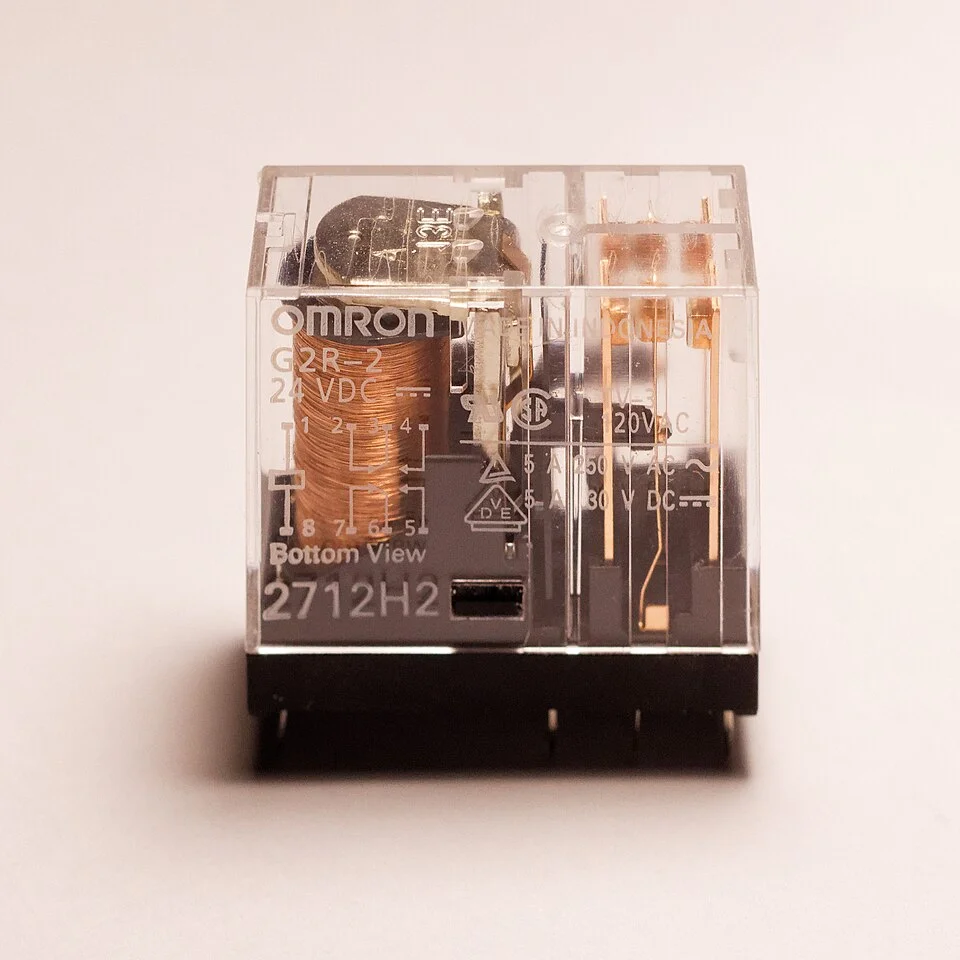
Example relay showing a coil and contacts. The photograph does not depict a tested suppression circuit.
Three events that must not be conflated
Coil current decay, armature release and contact transfer are related, but they are not the same event.
- Coil current decay begins when the drive is removed and the current finds a suppression path. The winding’s resistance, inductance, magnetic state and clamp voltage affect the waveform.
- Armature release occurs when the magnetic force is no longer sufficient to hold the mechanism against its restoring forces. It can occur while measurable coil current remains. Inductance can also change as the armature moves.
- Contact transfer is the mechanical and electrical change at the contacts. A normally open contact may open, a normally closed contact may close, or both may change in a changeover relay. The transitions can include bounce, and their sequence depends on the relay design.
A faster initial current decay is therefore not a measured contact-release time. Contact opening, closure, final settling and bounce can occur at different times. Use the exact relay manufacturer’s timing definitions when comparing datasheet values with project measurements; a specified release time may not include bounce.
Establish the current path and voltage references
Call the positive-supply coil terminal A and the switched coil terminal B. The low-side switch connects B toward ground when on. In normal energization:
- Conventional current flows from the positive supply into A, through the coil from A to B, then through the switch to ground.
- B is near ground, subject to switch and wiring voltage drops.
- The coil voltage, expressed as VA-VB, is positive.
At turn-off, winding current initially continues in the same direction through the coil, from A to B. To sustain that current, the winding reverses its terminal voltage: B rises above A until a suppression path conducts. The resulting loop and voltage depend on where the clamp is connected.
Two voltage references matter:
- Coil-relative voltage: VB-VA, which describes the reverse voltage across the coil and an across-coil clamp.
- Ground-referenced switch-node voltage: VB-Vground, which includes the supply voltage as well as the coil-relative clamp voltage.
For an across-coil clamp, the switch node can therefore rise approximately to the actual supply-terminal voltage plus the clamp voltage, before considering wiring, switching overshoot and ringing. A clamp described by its voltage across the coil is not automatically safe for a switch with the same ground-referenced voltage rating.
For a MOSFET, also check drain-to-source voltage at the device pins. If the source is not exactly at the chosen ground reference—for example, because of a sense resistor or trace inductance—switch-node voltage to ground and drain-to-source voltage are not identical.
Antiparallel diode: low voltage, longer decay
An antiparallel diode connects anode to B and cathode to A. While the coil is energized, that diode is reverse-biased. When the switch opens and B rises above A, the diode conducts:
A → coil → B → diode → A
In this idealized local loop, current circulates through the winding and diode rather than continuing through the open switch. The coil-relative reverse voltage is approximately the diode’s forward voltage while it conducts; the ground-referenced voltage at B is approximately the voltage at A plus that forward voltage.
The low reverse voltage generally makes current decay more slowly than a properly conducting higher-voltage clamp. Winding resistance still dissipates energy, and the diode’s forward voltage varies with current and temperature. The simple picture does not establish when the armature releases or when contacts settle.
The diode must tolerate the applicable reverse voltage, current, pulse behavior, temperature and repetitive operation. Its low clamp voltage is useful for switch-voltage margin, but it is not proof of acceptable contact timing or complete protection against every transient.
Check whether the selected relay already contains a diode or another suppression element. A built-in diode makes coil polarity significant even when an otherwise similar bare coil is not polarized; reversing it can create an unintended supply path.
Higher-voltage clamps: more voltage to evaluate
A higher reverse voltage across the coil generally produces a faster current reduction than a plain diode, all else being equal. The actual waveform depends on winding resistance, changing inductance, clamp characteristics and parasitics. Several topologies are possible; their current paths are not interchangeable.
| Candidate in this low-side circuit | Turn-off path and approximate switch-node voltage | Main decision to verify |
|---|---|---|
| Diode across the coil | B through the diode to A; node B is approximately the supply at A plus diode forward voltage | Low voltage stress versus slower current decay and measured contact behavior |
| Series diode and zener across the coil | B through the forward diode and reverse-breakdown zener to A; node B is approximately the supply plus their conducting voltages | Dynamic clamp voltage, driver margin, pulse and repetitive thermal limits |
| Bidirectional TVS across the coil | B through the TVS to A; node B is approximately the supply plus TVS clamping voltage | Standoff at maximum normal coil voltage and clamping voltage at the actual pulse current |
| Clamp across the low-side switch | B through the clamp and return path, including the supply, to A; node B is approximately the switch-side clamp voltage | Clamp voltage relative to supply, supply behavior, switch stress and energy in the complete loop |
These are first-order descriptions, not guaranteed peaks. Include actual supply variation, device tolerances, current-dependent clamp behavior, wiring and overshoot. A clamp candidate is not approved until its electrical limits and contact response have been verified.
Series diode and zener across the coil
One across-coil arrangement has a diode and zener in series, with the following turn-off path:
B → diode anode-to-cathode → zener cathode-to-anode → A → coil → B
The ordinary diode conducts forward and the zener conducts in reverse breakdown. During normal energization, the series diode blocks the opposite direction. During suppression, the coil-relative clamp is approximately the zener’s dynamic voltage plus the diode’s forward voltage.
The relevant zener voltage is not just its nominal marking: it varies with current, tolerance and temperature. The series diode also needs appropriate reverse-voltage and pulse-current capability. At B, the switch must withstand the supply voltage plus the actual clamp voltage and any overshoot.
TVS arrangements
A suitably rated bidirectional TVS across A and B can clamp the voltage across the coil. It sees the normal coil voltage during energization, so its standoff and leakage behavior must be checked over the full supply and temperature range, not only during turn-off.
Polarity is important with a unidirectional TVS. Placing one directly across the coil with its cathode at B and anode at A would put it in the forward-conducting direction during normal energization. A series blocking diode or a different, properly analyzed topology may be needed. “TVS across the coil” is not a complete polarity specification.
A TVS can instead be connected across the low-side switch, subject to the actual circuit and device limits. In that case the turn-off path can be:
A → coil → B → switch-side clamp → ground/return → supply → A
Unlike the ideal across-coil loop, this path includes the supply, which can contribute energy while current continues. The coil's reverse voltage is approximately the switch-side clamp voltage minus the supply voltage; the switch sees the clamp voltage itself, not that clamp voltage plus the supply. The clamp must also stay out of conduction in normal circuit states and provide enough voltage above the supply for the intended decay. Rail variation, return-path impedance and the supply’s behavior matter.
Qualified internal driver clamp
An internal clamp may simplify the external circuit, but its name alone does not define its current path or safe operating envelope. A driver might clamp relative to a supply pin, across its output device, or by another mechanism. Determine the path from the exact driver datasheet and circuit, including supply and ground pins.
Check whether the manufacturer qualifies the relevant repetitive inductive-switching operation. A one-time absolute-maximum avalanche or transient statement is not, by itself, permission for continuous repetitive use. Internal dissipation and junction temperature may be decisive.
Check limits and energy before comparing timing
Use the exact relay, switch or driver, suppression device and circuit revision. Account for minimum and maximum supply voltage, tolerance, temperature, aging allowances where applicable, and expected switching frequency.
For the relay, check its coil operating range, thermal and duty requirements, polarity restrictions where applicable, and any specified transient, insulation or reverse-voltage limits. Check contact ratings separately for the actual load and switching conditions.
An alternate relay, driver or clamp is a design change, not an automatic equivalent. Use a controlled component substitution approval process to review the exact part, relevant pulse conditions and required retesting before release.
For the driver or switch, check normal operating limits and absolute maximums, including output voltage, current, temperature and any applicable transient, safe-operating-area or repetitive-clamp limits. Absolute maximum ratings are boundaries, not desired operating targets. Allow for clamp tolerance, dynamic voltage at the actual current, supply variation and measured overshoot; nominal zener or TVS voltage alone is insufficient.
For the clamp, evaluate pulse current, pulse energy, repetitive power and temperature. Average power estimated from energy per event times event rate is useful, but it does not replace pulse-rating and thermal checks. Current and voltage vary throughout the event, and clamp losses are not necessarily equal to all stored coil energy.
Hypothetical energy calculation—not a component selection
Assume, solely for illustration, a constant inductance of L=0.1 H and an initial current of I=0.2 A:
This is 0.002 J of assumed initial magnetic energy, not a measured relay value or an actual release-time calculation. A real relay’s inductance can change with current and armature position. Energy can be distributed among the winding, clamp, switch, mechanical motion and other losses. Depending on the topology, the supply can also contribute energy during turn-off. The calculation alone does not size a component or establish repetitive heating.
Contact-load protection is a separate problem
Coil suppression addresses energy and voltage associated with turning off the coil circuit. It does not automatically suppress an inductive load switched by the relay contacts.
A contact-side load can generate its own voltage transient and arc when interrupted. Its protection must be evaluated for that load, its supply, contact configuration and required response. A load-side suppressor may itself alter load release behavior. Do not infer contact life, arc control or load protection from the coil clamp choice.
Release worksheet: evidence to collect
No actual test, validated circuit or bill of materials has been obtained here. The following is an unfilled evidence-collection worksheet, not a record of results. Define pass criteria and an approved procedure before testing. Refer live or hazardous testing to qualified personnel using approved procedures; do not improvise live-mains measurements.
| Item | Evidence to collect |
|---|---|
| Exact hardware | Relay manufacturer and full part number; driver or switch and clamp part numbers; PCB and schematic revisions; assembly and wiring details. |
| Circuit path | Verified A and B connections, suppression polarity, supply and return paths, switch source reference, and any internal clamp behavior documented for the exact driver. |
| Conditions | Approved supply range, temperature, coil duty and switching rate; contact configuration and representative load or approved safe contact-sensing arrangement. Record relevant extremes and tolerances. |
| Procedure and safety | Approved test plan, equipment ratings, isolation method, personnel qualifications, sample plan and stop conditions. Use appropriate isolation and rated differential or current probes; an oscilloscope’s ground connection must not create an unintended circuit path. |
| Time reference | Defined turn-off command and threshold, with the same reference used to compare current, voltage and contact events. Record instrument bandwidth, sample rate and trigger settings. |
| Coil current | Probe location, direction and reference; initial current, decay waveform and current at relevant mechanical or contact events. Assess whether a shunt or probe changes the circuit. |
| Switch voltage | Measure and label B-to-ground, B-to-A and, where applicable, switch drain-to-source using suitable probes and reference points. Capture clamp level, peak, ringing and duration. |
| Contact transition | Record initial NO/NC states and first opening or closure, final stable state and bounce. Define the sensing thresholds and distinguish first transition from settled transfer. |
| Acceptance | Predefine allowable driver and clamp stress, temperature, release and settling times, bounce, contact behavior and project-specific EMI limits and measurement methods. Specify how variation across units and conditions will be assessed. |
Correlating the waveforms is the decision point: a clamp is a candidate only if its measured contact behavior and electrical stresses meet the project’s predefined criteria across the approved conditions. Fast voltage edges can increase ringing or radiated/conducted interference even when they improve current decay. Probe bandwidth, loop area, grounding and layout can distort or create apparent peaks, so measurement setup is part of the evidence.
Before layout release, identify safe measurement access using the PCB test-point planning considerations. For an oscilloscope measurement, check the probe's differential and common-mode voltage ratings, transient category and bandwidth against the complete setup. A protective-earth-referenced probe ground clip must not be attached to a floating switch node: it can create an unintended short. The oscilloscope overview is background on the instrument; the approved test procedure and probe documentation govern the actual setup.
Use the functional test plan to define the commanded state, contact load, timing thresholds and records. The test coverage matrix can help distinguish planned checks from demonstrated detection. For interference investigation, the related EMI reduction discussion addresses source, path and victim; passing a relay timing check does not establish EMC compliance.
Assembly and release handoff
The design owner defines the circuit, device limits, safe test procedure and product qualification criteria. The assembly and test teams work to the agreed drawings, BOM, procedures and inspection scope; product release remains with the responsible project authority. If a part or waveform differs from the approved baseline, preserve the configuration and evidence for component failure investigation before deciding on disposition.
For an assembly quote request, provide the schematic and PCB revisions, full relay, driver and clamp part numbers, polarity markings, approved alternatives, operating conditions and intended test coverage. Identify the requested records and ask which inspection and test steps can be included in the quotation; a quotation or assembly inspection does not by itself qualify the end product.
FAQ
Does coil current have to reach zero before the relay releases?
No. The armature can release while current remains. The release point depends on magnetic and mechanical conditions, and the contacts may continue moving or bouncing afterward.
Is a higher clamp voltage always better?
No. It can accelerate current decay but raises voltage stress and may change EMI, clamp heating and contact dynamics. Acceptability depends on the exact parts, topology and measured behavior.
Can I compare a coil-clamp voltage directly with a switch voltage rating?
Not without checking references. An across-coil clamp voltage is relative to the supply-side coil terminal; the low-side switch node can see the supply voltage plus that clamp voltage and overshoot.
Does an internal driver clamp eliminate external protection checks?
No. Its path, voltage, repetitive-energy capability and thermal limits must be established from the exact driver documentation and operating conditions. An internal clamp is not necessarily qualified for every relay load or switching rate.
Does a diode across the coil protect the relay contacts?
Not from every contact-side load transient. Coil suppression and load-side protection address different energy paths and must be evaluated separately.