
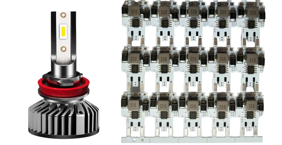
A reverse light PCB is a critical electronic assembly inside an automotive lighting module. Although the board is usually compact, it must handle several engineering requirements at the same time: driving high-brightness LEDs, managing heat, protecting electronics from vehicle transients, maintaining optical alignment, and supporting consistent high-volume production.
The PCB is only one part of the complete reverse lamp system. The final performance depends on the interaction between the LED package, driver circuit, optical lens, reflector, connector, enclosure, thermal interface, sealing design, and vehicle electrical system.
A well-designed reverse light PCB improves the probability of passing thermal, optical, electrical, and reliability validation. However, PCB design alone does not guarantee compliance with vehicle lighting regulations. Approval depends on the complete lamp assembly, including optical output, environmental durability, electrical performance, and customer-specific validation requirements.
For automotive PCB manufacturers, the practical design goal is clear: create a board that delivers stable LED performance, manages heat efficiently, survives vehicle operating conditions, and can be manufactured consistently at production volume.
Key takeaways
- Reverse light PCBs require careful thermal design because high-power LEDs generate concentrated heat inside compact lamp housings.
- Metal Core PCB, especially aluminum MCPCB, is commonly used because it provides a short thermal path from LED packages to the lamp structure.
- LED driver selection affects efficiency, temperature rise, EMI performance, and protection requirements.
- Automotive protection circuits must be considered during PCB layout. TVS placement, grounding, filtering, and current paths directly affect transient performance.
- Optical performance depends on PCB manufacturing accuracy. LED position, solder volume, board flatness, and assembly control influence the final beam pattern.
- Production reliability depends on process control, including solder quality, AOI inspection, electrical testing, thermal verification, and traceability.
In this guide
- What a reverse light PCB does in the lamp system
- Main design challenges
- MCPCB and thermal path design
- LED driver and electrical protection
- Optical layout and manufacturing repeatability
- Automotive environment and reliability planning
- PCBA manufacturing and test flow
- Cost drivers and RFQ checklist
- Standards and validation boundaries
- FAQ
What a reverse light PCB does in the lamp system
A reverse light PCB connects and supports the LED array, driver circuit, protection components, connector interface, and optional control electronics. Depending on the lamp architecture, the board may include only LED packages and current-control components, or it may contain advanced functions such as temperature sensing, diagnostics, PWM dimming, and communication interfaces.
The PCB must perform four primary functions:
| PCB function | System impact | Main design consideration |
|---|---|---|
| Thermal management | LED lifetime, brightness stability, color consistency | MCPCB structure, copper area, thermal pad design, housing interface |
| Current regulation | LED brightness and reliability | Constant-current driver, resistor accuracy, power dissipation |
| Electrical protection | Resistance to vehicle electrical events | TVS protection, filtering, reverse-polarity protection, grounding |
| Optical positioning | Beam quality and output consistency | LED location, solder height, assembly tolerance |
A reverse light PCB differs from many low-power lighting boards such as Accent Light PCB designs. Exterior vehicle lighting requires higher control of temperature, durability, and production variation because performance must remain stable throughout the vehicle service life.
Main design challenges
Reverse light PCB projects often appear simple because the circuit may contain only LEDs and a driver. The actual engineering difficulty appears when the board operates inside a sealed automotive lamp housing.
1. Heat concentration in compact lamp assemblies
LED efficiency has improved significantly, but a large percentage of electrical input power still becomes heat. If the thermal path is insufficient, the LED junction temperature increases and can cause:
- Reduced light output.
- Color shift.
- Faster LED aging.
- Driver overheating.
- Reduced reliability margin.
The PCB provides an important thermal path, but it cannot solve poor enclosure design or inadequate heat transfer to the outside environment.
2. Automotive electrical transients
Vehicle power systems experience conditions that do not exist in normal laboratory testing. Reverse light electronics may encounter:
- Battery voltage variation.
- Load dump events.
- Jump-start conditions.
- Reverse battery connection.
- Electrostatic discharge.
- Conducted electrical noise.
Protection devices must be positioned correctly in the PCB layout. A component that exists only on the schematic but is poorly connected physically may not provide effective protection.
3. Moisture, vibration, and temperature cycling
Exterior lamps are exposed to harsh conditions, including:
- Humidity and condensation.
- Road salt contamination.
- Vibration.
- Repeated heating and cooling cycles.
- Mechanical stress from connectors and mounting points.
These conditions affect solder joints, copper adhesion, surface finish, conformal coatings, and the connection between the PCB and lamp housing.
4. Optical sensitivity
The optical system depends on accurate LED placement. Small differences in LED height, rotation, or position can change the final light distribution.
Electrical testing may pass while optical performance fails because of:
- LED placement offset.
- Uneven solder volume.
- PCB warpage.
- Incorrect pad geometry.
- Assembly variation.
5. Cost and production balance
Automotive lighting boards are usually produced in high volumes. Overengineering increases cost, while insufficient thermal or electrical design creates validation failures.
The correct solution matches the PCB structure to the actual:
- LED power.
- Operating temperature.
- Housing design.
- Reliability target.
- Production volume.
MCPCB and thermal path design
For many reverse light modules, Metal Core PCB is the preferred substrate technology. An MCPCB typically consists of a copper circuit layer, thermally conductive dielectric layer, and aluminum or copper metal base.
The substrate transfers heat away from LED packages while maintaining electrical isolation.
Common substrate choices
| Substrate option | Suitable application | Main advantage | Design limitation |
|---|---|---|---|
| FR-4 PCB | Low-power indicators and control boards | Low cost and common manufacturing process | Limited thermal performance |
| Aluminum MCPCB | Most automotive LED lighting modules | Good thermal and cost balance | Requires correct dielectric specification |
| Copper core PCB | High-power compact modules | Excellent heat spreading | Higher cost and weight |
| Ceramic PCB | Extreme thermal applications | High thermal stability | Expensive and mechanically sensitive |
For most reverse lighting applications, aluminum MCPCB provides sufficient thermal performance when LED power, current level, and housing design are correctly matched.
Copper and ceramic substrates should be selected only when supported by measured thermal data, simulation results, or customer reliability requirements.
Thermal path evaluation
The complete thermal chain should be reviewed:
- LED junction to LED thermal pad.
- LED pad through solder joint.
- PCB copper land spreading.
- Copper layer to MCPCB dielectric.
- Dielectric transfer to metal base.
- Metal base connection to housing.
- Housing heat dissipation to ambient air.
A high-performance PCB can still fail if the enclosure has poor thermal contact or the thermal interface material is incorrectly applied.
Thermal layout recommendations
- Place high-power LEDs where heat can spread efficiently.
- Maximize copper spreading where allowed by the LED package design.
- Avoid narrow thermal bottlenecks.
- Separate temperature-sensitive components from LED hotspots.
- Define dielectric thermal conductivity and insulation requirements in the PCB specification.
- Validate with physical temperature measurements.
For higher current lighting assemblies, High Thermal Conductivity PCB and Heavy Copper PCB options may be considered when current density and temperature rise justify the additional cost.
LED driver and electrical protection
A reverse light PCB requires stable LED current control and protection against automotive electrical stress.
The driver architecture depends on:
- Input voltage range.
- LED configuration.
- Required brightness stability.
- Thermal limitations.
- EMI requirements.
- Diagnostic functions.
Driver options
| Driver type | Suitable application | Advantage | Limitation |
|---|---|---|---|
| Resistor-limited LED string | Low-cost low-power modules | Simple design | Poor current stability |
| Linear constant-current driver | Moderate power LED boards | Low EMI and simple layout | Generates additional heat |
| Switching LED driver | Higher power modules | High efficiency | Requires careful EMI design |
| Smart LED driver | OEM systems with diagnostics | Monitoring and control capability | Higher complexity |
The PCB must support the selected driver technology. Linear drivers require thermal planning because excess voltage is converted into heat. Switching drivers require controlled current loops, proper grounding, and EMI management.
Protection strategy
| Electrical risk | Protection method | PCB review point |
|---|---|---|
| Reverse polarity | Diode or MOSFET protection | Power loss and thermal impact |
| Voltage surge | TVS diode and filtering | Place protection near input connector |
| ESD event | ESD protection devices | Minimize return path inductance |
| EMI noise | LC filtering and layout control | Control switching loops |
| Overtemperature | NTC sensing or thermal shutdown | Sensor location accuracy |
| LED fault | Driver diagnostics | Match customer requirements |
Protection components must be physically close to the stress entry point. A TVS diode located far from the connector may not clamp transient energy effectively.
Optical layout and manufacturing repeatability
The PCB establishes the mechanical position of the LED source. Because automotive optics are sensitive to alignment, manufacturing consistency directly affects light output.
LED placement and pad design
LED pad design must consider:
- Thermal transfer.
- Solder volume.
- Void control.
- Package alignment.
- Reflow process capability.
A board can pass electrical inspection but still produce inconsistent optical output if LED placement varies between assemblies.
Solder mask and surface finish
White solder mask is commonly used around LED areas because it can improve optical reflection. However, the material must withstand:
- LED operating temperature.
- Reflow processing.
- Long-term environmental exposure.
Surface finish selection also affects solder reliability.
| Surface finish | Benefit | Consideration |
|---|---|---|
| OSP | Flat surface and low cost | Limited shelf life |
| Lead-free HASL | Good solderability | Reduced flatness compared with ENIG |
| ENIG | Flat surface and reliable soldering | Higher cost |
| ENEPIG | Suitable for demanding applications | Usually unnecessary for standard reverse lamps |
Automotive environment and reliability planning
Reverse light PCBs should be designed for the complete vehicle environment rather than only bench operation.
Environmental reliability factors
| Stress condition | PCB design consideration |
|---|---|
| Temperature cycling | Copper adhesion, solder fatigue, material compatibility |
| Vibration | Connector support, mounting strength, solder joint reliability |
| Moisture exposure | Surface protection, sealing design, corrosion resistance |
| Thermal aging | LED junction temperature and material selection |
| Chemical exposure | Coating and material compatibility |
Reliability validation should evaluate the actual lamp assembly, because PCB performance depends on the enclosure and operating environment.
PCBA manufacturing and test flow
A reliable reverse light PCB requires controlled manufacturing processes.
Recommended production controls
| Process step | Purpose |
|---|---|
| Incoming material inspection | Verify PCB, LED, and component specifications |
| Solder paste inspection (SPI) | Control solder volume |
| Automated optical inspection (AOI) | Detect assembly defects |
| Reflow profile validation | Protect LED and solder reliability |
| Electrical test | Verify current, voltage, and functionality |
| Thermal inspection | Confirm temperature performance |
| Traceability control | Support quality investigation |
For LED assemblies, solder void control is especially important because voids under thermal pads increase thermal resistance.
Cost drivers and RFQ checklist
A complete RFQ package helps prevent redesign during manufacturing.
Important RFQ information
| Item | Required information |
|---|---|
| Application | Reverse light, tail lamp, auxiliary lamp, or other LED module |
| LED specification | Package type, forward voltage, current, thermal data |
| PCB type | FR-4, aluminum MCPCB, copper core, ceramic |
| Layer structure | Copper thickness, dielectric thickness, stackup |
| Mechanical data | Board outline, mounting holes, connector location |
| Thermal requirement | Maximum temperature, heat sink interface |
| Electrical requirement | Input voltage, protection, driver type |
| Production volume | Prototype, low volume, mass production |
| Testing requirement | AOI, electrical test, thermal validation |
Main cost drivers include:
- PCB material selection.
- Copper thickness.
- LED package type.
- Driver complexity.
- Assembly yield.
- Testing requirements.
- Volume.
Standards and validation boundaries
Automotive lighting validation applies to the complete lamp system. The PCB supplier should support electrical, thermal, and manufacturing validation, but the final product must be evaluated according to the customer's required regulations and vehicle standards.
Typical engineering reviews include:
- Electrical input behavior.
- Thermal performance.
- EMC evaluation.
- Environmental durability.
- Optical output testing.
- Production consistency.
The exact requirements depend on vehicle manufacturer specifications, regional regulations, and lamp application.
FAQ
What PCB material is commonly used for reverse LED lights?
Aluminum MCPCB is commonly used because it provides a practical balance between thermal performance, cost, and manufacturability. Higher-performance materials such as copper core or ceramic PCB may be selected for higher power applications.
Can FR-4 PCB be used for a reverse light?
FR-4 can be used for low-power LED modules or control boards, but it is usually not the first choice for high-brightness LED arrays because its thermal conductivity is much lower than metal core PCB materials.
Why does a reverse light PCB need a constant-current driver?
LED brightness and lifetime depend strongly on current control. A constant-current driver reduces brightness variation caused by voltage changes and temperature effects.
Is PCB design responsible for optical performance?
The PCB does not define the complete optical output, but it strongly affects LED position, height, and repeatability. Poor PCB manufacturing control can create optical variation even when the circuit functions correctly.
What information should be provided when requesting a reverse light PCB quote?
A manufacturer should receive LED specifications, PCB material requirements, mechanical drawings, electrical requirements, expected production volume, testing requirements, and thermal conditions.
How can reverse light PCB reliability be improved?
Reliability improves when thermal design, electrical protection, material selection, assembly control, and validation testing are considered together rather than optimized separately.