

Rogers 4350B is chosen when a design has outgrown FR-4 in terms of loss, phase stability and temperature drift, but still needs a process that fits modern PCB lines. At that point the question is not “what is this material”, but whether your Rogers 4350B PCB manufacturer can turn the layout into stable, repeatable hardware from prototype through to volume.
HILPCB is a PCB manufacturing and PCB assembly factory focused on RF, microwave and high-speed designs. We provide Rogers 4350B PCB fabrication, Rogers 4350B PCB assembly and related board types—standard FR-4, high-Tg FR-4, other Rogers PCBs and Teflon PCBs—so that RF front-ends, radar modules, backhaul links and mixed-signal platforms can be built on a single, coherent manufacturing base.
1. What matters technically when you move to Rogers 4350B
Most teams adopt Rogers 4350B because they need:
- a controlled dielectric constant for predictable impedance and phase
- lower loss than FR-4 at GHz frequencies
- more stable behaviour over operating temperature
Those advantages only appear in real hardware if the Rogers PCB manufacturing process keeps the material inside a well-defined and repeatable performance window. As an RF PCB manufacturer working with Rogers 4350B, we focus on three main dimensions.
1.1 Impedance accuracy
On impedance-critical layers we apply:
- tight line-width and spacing control, with layer-specific etch compensation
- verified copper weights and plating thicknesses
- monitored critical dimension (CD) ranges for 50 Ω, 75 Ω and differential 90–100 Ω structures
This makes the simulated impedance model behave similarly on the finished board, batch after batch.
1.2 Dielectric thickness and stack-up control
For Rogers 4350B PCB production, we align the physical stack-up to the one used in EM simulation:
- match core and prepreg thicknesses to the intended dielectric spacing
- define tolerances that keep differential delay, phase and S-parameters within the acceptable window
- stabilise lamination profiles for hybrid builds that combine Rogers 4350B with FR-4 or high-Tg FR-4
This is part of our broader high-frequency PCB manufacturing approach: the stack-up is treated as part of the circuit, not just a mechanical structure.
1.3 Copper and surface characteristics
Conductor loss and copper roughness become important at multi-GHz frequencies. In our microwave PCB fabrication processes we:
- select suitable copper foils (standard or low-profile) according to your loss budget
- control etch profiles to avoid neck-downs and jagged edges on RF lines
- keep surface finish choices (ENIG, immersion silver, OSP) consistent with both RF performance and assembly requirements
In other words, Rogers 4350B PCB fabrication is not just “using a different laminate”, but engineering a controlled impedance and loss environment that can be reproduced across builds.
2. Stack-up and transmission line design on Rogers 4350B
For high-frequency and high-speed designs, the PCB stack-up is part of the circuit. A capable Rogers 4350B PCB supplier must be able to translate the electrical intent of the stack-up into a manufacturable structure.
2.1 Placing Rogers 4350B where it really adds value
A typical high-frequency stack-up will:
- use Rogers 4350B on the layers that carry RF microstrip, stripline, GCPW or critical high-speed pairs
- use FR-4 or high-Tg FR-4 on control and power layers where dielectric performance is less critical
- maintain consistent reference planes, return paths and shielding between RF and digital domains
We routinely help customers refine mixed-material multilayer circuit board stack-ups so that Rogers 4350B is applied exactly where it improves RF performance or timing, while the rest of the board remains cost-effective.
2.2 Line structures and impedance control
In our high-frequency PCB manufacturing work with Rogers 4350B, the most common transmission line types are:
- surface microstrip for PA outputs, matching networks and antenna feeds
- embedded stripline for shielded RF channels and high-speed serial links
- grounded coplanar waveguide (GCPW) to confine fields and improve isolation
- coupled lines and differential pairs for filters, couplers and high-speed buses
For each of these structures we align:
- finished line width and spacing
- dielectric thickness between trace and reference plane
- effective Dk, including the impact of solder mask where present
- copper thickness and plating build-up
When you provide us with your stack-up intent and target impedances, we check geometries against our actual Rogers 4350B PCB fabrication capabilities and, where appropriate, add impedance coupons so that each lot can be verified by TDR or network analysis.
If you want to pre-check your data before sending, you can use our online gerber viewer and 3D PCB viewer to confirm layer assignments, apertures and stack-up details.
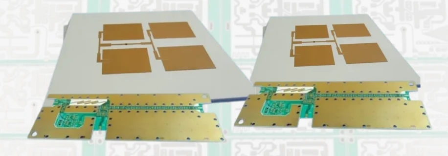
3. From prototype to volume: making Rogers 4350B scalable
A successful RF project rarely stops at a single prototype. It must move through engineering samples, pilot runs and then stable volume. The challenge is to keep electrical behaviour and manufacturability aligned across all stages, using the same Rogers 4350B PCB manufacturer.
3.1 Early builds: engineering samples and small batches
In early stages, priorities are fast feedback and design iteration. Using our small-lot lines and small-batch assembly capability, we support:
- short-run Rogers 4350B PCB fabrication for two- to multi-layer RF and mixed-signal boards
- partial population (for example, only the RF section) to focus on validating front-end performance
- rapid turns of design tweaks to stack-up, line width or pad geometry, backed by direct feedback from fabrication and assembly engineers
Because the same process baseline is used later for volume, the data gathered during these early builds directly feeds into process windows for Rogers 4350B PCB production.
3.2 Scaling up: controlled migration to larger volumes
Once the design is stable, we expand capacity rather than reinventing the process. That means:
- keeping the same Rogers 4350B material set and stack-up structure
- moving to higher-capacity lines under the same process controls and quality system
- tightening in-process monitoring and lot-to-lot checks on impedance, layer registration and drill quality
For mature products, our large-volume assembly route can support continuous series builds under one controlled release package. The goal is to keep the approved material, stack-up, process, and acceptance evidence consistent from early samples through production.
4. System-level builds: more than one Rogers 4350B board
Real products seldom consist of a single RF card. Around the Rogers 4350B core there are usually several other board types and interconnects. Typical combinations we support include:
- Rogers 4350B RF and microwave cards for front-end, filters, couplers and power stages
- FR-4 digital control and processing boards with MCUs, FPGAs or processors
- power boards with heavier copper or thermal design for bias networks and DC-DC stages
- backplanes or motherboards carrying high-speed links and clock distribution
- rigid-flex or flex circuits connecting RF boards to antennas, sensors or front panels
Because we act both as an RF PCB manufacturer and as a general PCB shop, we can keep:
- mechanical interfaces consistent (board thickness, connector heights, back-drill depths, shield-can footprints)
- system-level impedance and routing rules aligned across different board types
- responsibility for issues clear, since both bare boards and assemblies come from the same engineering team
For customers, this turns the Rogers 4350B PCB manufacturer into a system-level partner, not just a single-board vendor, and reduces friction when debugging complex RF systems.
5. Rogers 4350B PCB assembly and module delivery
Rogers 4350B boards almost always carry sensitive RF components and packages that benefit from an assembly flow tuned to the laminate and stack-up. HILPCB provides Rogers 4350B PCB assembly as part of a one-stop solution.
5.1 SMT and RF component handling
Our assembly lines regularly handle:
- RF ICs, MMICs, LNAs, PAs, mixers and synthesizers in QFN, BGA and other fine-pitch packages
- precision RF connectors (SMA, SMP, edge-launch and board-to-board)
- shield cans, cavity structures and mechanical frames for isolation
- mixed assemblies where a single panel combines Rogers 4350B RF regions and FR-4 digital or power regions
Reflow profiles and handling rules are adapted to mixed-material stacks so that thermal stress on vias and pads is controlled across the board.
5.2 Microwave PCB fabrication plus assembly as a single chain
By combining microwave PCB fabrication on Rogers 4350B with in-house assembly, we can:
- control solder-mask openings and pad geometries with knowledge of real assembly constraints
- resolve questions about yield or RF performance from both the board and assembly sides without supplier hand-offs
- extend the scope from individual boards to sub-assemblies and complete modules where required
For programs that need a higher level of integration, we can take Rogers PCB manufacturing as the starting point and deliver fully assembled units—using our box-build assembly and turnkey assembly services—covering mechanical integration, cabling and final test under a single project structure.
6. Information that helps us build your next Rogers 4350B design
To give useful feedback and accurate quotations on Rogers 4350B PCB manufacturing, it helps if you can share:
- target frequency bands and main use case (base-station RF, radar, backhaul, instrumentation, etc.)
- stack-up intent: which layers should be Rogers 4350B, which can remain FR-4 or other materials
- impedance targets and line types (microstrip, stripline, GCPW, differential pairs)
- expected quantities at each stage: prototypes, small batches, ramp-up and mature volume
- whether you need bare boards only, or a full Rogers 4350B PCB assembly and module build
With this information, HILPCB can review feasibility, refine the stack-up, align simulations with stated process parameters, and plan the path from first articles to stable, repeatable PCB production using the specified Rogers 4350B laminate. Material availability and evidence are confirmed per quotation.
If you are planning a new RF or microwave design on Rogers 4350B, or migrating an existing design to this laminate, you are welcome to contact HILPCB. Our goal is to provide Rogers 4350B PCB fabrication, Rogers 4350B PCB assembly and complete high-frequency PCB manufacturing that behave like an extension of your design process—turning models and layouts into hardware that performs as intended, from the first prototype through to volume shipments.
Common Questions
Why is Rogers 4350B widely used in RF and microwave PCB designs?
Rogers 4350B offers low dielectric loss, stable electrical behavior, and manufacturing characteristics that support repeatable impedance control. That makes it a common choice for base-station RF, radar, instrumentation, and other high-frequency platforms.
Can Rogers 4350B be used only on selected layers?
Yes. Many designs use Rogers 4350B only where RF performance is critical and keep FR-4 on digital or power layers to control cost. The value comes from balancing material performance with a manufacturable hybrid stack-up.
What should be confirmed before moving a Rogers 4350B design into production?
It is important to align stack-up intent, impedance targets, drill and registration tolerances, assembly constraints, and expected volume stages. Early alignment helps keep the performance measured on prototypes consistent with later production lots.
Is it useful to source Rogers 4350B fabrication and assembly from one supplier?
Often yes, because RF boards frequently include sensitive connectors, shielding, and mixed-material structures. A single supplier can coordinate board fabrication and assembly decisions more closely, which reduces handoff risk during debug and scale-up.