
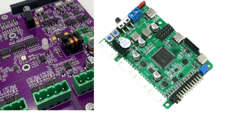
Selective wave soldering: managing real-time and safety redundancy challenges in industrial robotics control PCB
In the Industry 4.0 era, industrial robots are central to smart manufacturing. Control-system accuracy, real-time behavior, and reliability directly define productivity and safety. For motion control engineers, these attributes ultimately depend on a well-designed, reliably built control PCB. Here, Selective wave soldering becomes a critical process: it enables robust mixed-technology (SMT + THT) assembly and directly impacts long-term stability for servo drives, encoder feedback, and safety loops. A successful robotics controller must validate end-to-end across NPI EVT/DVT/PVT.
This article explains key industrial robotics control PCB challenges—from servo power paths and current-sense consistency, to high-speed encoder links, digital isolation in high dV/dt environments, braking thermal design, and EMC hardening—and how Selective wave soldering supports reliable manufacturing.
Servo drive loop: PWM, dead-time, and current-sense consistency
Servo drives are the robot’s “muscles”. The core is PWM control of the inverter bridge (IGBT/MOSFET).
PWM and dead-time control To prevent shoot-through, PWM inserts dead-time. It must be controlled precisely: too short risks shorting; too long distorts waveforms and causes torque ripple. PCB routing from controller to gate driver to power devices should be length-matched and symmetric so dead-time behavior is consistent across phases.
Current sensing: shunt vs. Hall sense Accurate current feedback enables advanced control like FOC.
- Low-side shunt sensing: cost-effective and linear, but needs precision differential amplification. Layout must use Kelvin connections to separate current path from sense path and remove lead resistance error.
- Hall sensors: provide natural isolation and fit high current, but cost more and can suffer temperature drift and nonlinearity.
In these high-power loops, large connectors, DC-link capacitors, and power modules are often THT parts. Selective wave soldering delivers localized, repeatable soldering of these joints without re-heating nearby precision SMT (op-amps, MCU), ensuring low impedance and high reliability of power paths—exactly what strong Turnkey PCBA services emphasize.
Encoder/resolver interfaces: RS-485, EnDat, BiSS-C layout essentials
If servo drive is muscle, encoders/resolvers are “nerves”—feeding accurate position/speed. Modern robots use high-speed serial absolute encoders (EnDat 2.2, BiSS-C) with data rates of Mbps and beyond.
High-speed differential routing These links typically use RS-485 physical layer differential pairs:
- Impedance control: keep differential impedance at 100Ω or 120Ω; this requires correct width/spacing/reference-plane distance. HILPCB high-speed PCB manufacturing supports tight impedance tolerance.
- Length match and coupling: intra-pair matching and tight coupling improve CMRR.
- Termination: place 120Ω termination at the receiver to absorb reflections.
Shielding and grounding Encoder cables are often shielded to resist motor EMI. On PCB, connect shield to chassis ground (FGND) via a low-impedance path (often using capacitors) to provide a noise drain.
Encoder connectors frequently face repeated mating cycles and mechanical stress, making them typical THT parts. Using Selective wave soldering produces fuller, more uniform, stronger joints than manual soldering—critical under vibration. After assembly, Boundary-Scan/JTAG can efficiently verify connectivity between MCU and the encoder-interface PHY, supporting quality assurance.
Encoder interface protocols: PCB design points (comparison)
| Feature | RS-485 (generic) | EnDat (Heidenhain) | BiSS-C (iC-Haus) |
|---|---|---|---|
| Physical layer | TIA/EIA-485-A | Based on RS-485, clock/data lines | Based on RS-422/485, clock/data lines |
| Topology | Bus (half-duplex) | Point-to-point (full-duplex) | Point-to-point or bus |
| Differential impedance | 120Ω | 120Ω | 100–120Ω |
| Layout key | Strict termination, avoid stubs | Clock/data pairs length-matched | Clock/data pairs length-matched, supports higher rate |
| Connector soldering | Selective Wave Soldering for mechanical strength | Selective Wave Soldering for SI robustness | Selective Wave Soldering for high-frequency stability |
Digital isolation and common-mode suppression: robust design under high dV/dt
Servo drives require isolation between high-voltage power side (often 48V–800V DC) and low-voltage control side (3.3V/5V). Isolation protects control electronics and operators, and blocks common-mode noise from switching.
Digital isolators Compared with optocouplers, modern digital isolators (capacitive/transformer coupling) offer higher speed, lower power, longer life, and stronger CMTI. In layout, both sides must be separated by a clear isolation barrier across all layers; isolation slots are often routed to increase creepage.
Creepage and clearance
- Creepage: shortest distance along an insulating surface.
- Clearance: shortest distance through air. Meet standards like IEC 61800-5-1, including internal-layer spacing in multilayer PCB.
Common-mode chokes Power input and motor output often use common-mode chokes to suppress noise. These are typically large THT parts; Selective wave soldering ensures reliable electrical and mechanical joints.
To further improve insulation and environmental robustness, Conformal coating adds a protective film on the PCB, resisting moisture/dust/salt fog and increasing surface insulation strength.
Braking unit and energy dissipation: balancing safety and thermal design
When joints decelerate or lower loads, motors can regenerate energy into the DC bus, raising bus voltage. A braking unit switches in a high-power braking resistor to burn energy as heat.
Braking loop design The braking loop includes a voltage comparator, driver, power switch (IGBT/MOSFET), and braking resistor. Key points:
- Voltage threshold: must be precise to avoid overvoltage without frequent false triggers.
- Power switch: needs fast response and sufficient current capability.
- Safety redundancy: braking is part of functional safety (e.g., E‑Stop) and often requires redundancy and fault detection.
Thermal management Braking resistors generate huge heat and become major PCB heat sources:
- Placement: keep resistors away from temperature-sensitive parts (electrolytic caps, MCU).
- Cooling: often use heavy copper PCB plus large copper areas as heatsinks; for high power, resistors may mount on external heatsinks.
Braking resistors and connectors are large THT parts; joint reliability is directly tied to system safety. Selective wave soldering provides consistent high-quality joints that survive thermal cycling and mechanical stress better than manual soldering.
Key braking-unit design points
- Safety first: braking is part of functional safety; run FMEA.
- Accurate monitoring: DC bus sampling must be fast and accurate, with filtering to prevent false triggers.
- Thermal management: evaluate peak/average power and design sufficient cooling to avoid overheating.
- Reliable assembly: solder quality of power resistors/connectors is critical; automated soldering is recommended.
- System integration: braking logic must align with motion planning and E‑Stop logic.
EMC robustness: ESD/EFT/surge and return-path control
Industrial environments contain strong EMI: EFT from relay switching, surge from lightning/large loads, and ESD from human contact. Robotics control PCB must deliver strong EMC robustness.
Protection devices and placement At every external interface (power, I/O, encoder), deploy TVS diodes, MOVs, or GDTs. Follow “protect first, filter after”, and keep the ground path short and wide to chassis ground.
Grounding, shielding, and return paths
- Ground strategy: single-point or hybrid grounding to merge analog/digital/power grounds at a controlled point to avoid ground loops. A solid ground plane provides a low-impedance return path.
- Return-path control: HF return current flows directly under the trace; ensure continuous reference planes under signals and avoid crossing splits.
- Shielding: locally shield sensitive circuits (analog sense, clocks) to reduce coupling.
Long-term reliability depends on both design and protection. A full Turnkey PCBA solution like HILPCB’s can engage early in NPI EVT/DVT/PVT to optimize EMC. After assembly, Conformal coating and Potting/encapsulation provide the final protection layer for harsh environments and improved insulation. Before applying these coatings, Boundary-Scan/JTAG is an efficient method to validate digital connectivity.
Conclusion
Industrial robotics control PCB is a complex system engineering task: balancing high-speed digital, precision analog, and high-power electronics. From PWM and current sensing to encoder SI, isolation, braking, and EMC, every step is challenging.
In this workflow, Selective wave soldering is an irreplaceable bridge between precise design and reliable reality. It ensures solder quality for key THT parts on mixed-technology boards—supporting stable and safe robot operation. To win in a competitive market, align excellent circuit design with advanced manufacturing. A partner like HILPCB, covering design review, prototyping, volume Turnkey PCBA, and value-add services like Potting/encapsulation, is a strong advantage.
Common Questions
Why is selective wave soldering important for industrial robotics control PCBs?
Robotics control boards often mix precision logic, power electronics, and heavy through-hole parts such as connectors, chokes, and braking components. Selective wave soldering helps create repeatable joints on those parts without overheating surrounding mixed-technology circuitry.
Which reliability risks are most critical on these boards?
Electrical noise, thermal cycling, vibration, and insulation stress are usually the biggest concerns. A weak joint on a power or control interface can become both a reliability issue and a safety issue in industrial service.
Can solder quality affect braking or motion-control safety functions?
Yes. Braking circuits, power interfaces, and signal connectors depend on stable mechanical and electrical connections. Poor solder quality can increase heat, create intermittent faults, or reduce long-term robustness in motion-control systems.
What should teams review before releasing a robotics control PCB to manufacturing?
They should review isolation rules, thermal design, selective-solder access, pallet strategy, EMC protection, and downstream testing. In industrial control hardware, manufacturability and safety performance have to be planned together.