
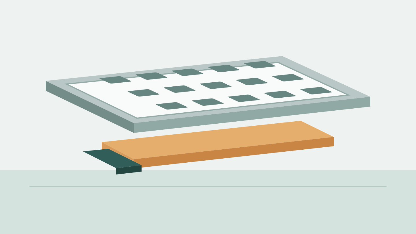
Start with a conservative, process-specific wipe recipe, then validate it against print quality across the whole interval—not just the first board after cleaning. Compare SPI distributions immediately before and after wipes, inspect residue, and check board support, gasketing, stencil condition and material compatibility before changing the interval.
Dry, vacuum and wet passes remove or manage contamination in different ways. None is mandatory in every process, and no pass order, solvent or number of boards per wipe works universally. The selected recipe must be permitted by the equipment and materials and meet agreed product and process criteria under documented trial conditions.
Underside wiping is also different from cleaning a rejected PCB. Wiping maintains the stencil between prints; a rejected board needs a separate disposition and, if permitted, a controlled cleaning and reprint procedure.
What an underside wipe is meant to control
During printing, solder paste can collect on the stencil underside or in apertures. Inadequate contact between the stencil and PCB can allow paste to spread where it should not. Residue may contribute to poor release, irregular deposits or bridging, although those symptoms can also have other causes.
An automatic underside-cleaning system brings wiping material into contact with the stencil underside. Depending on the printer and selected recipe, it may use solvent, vacuum, or both. The purpose is to restore a usable printing condition without damaging the stencil or introducing incompatible residue.
Cleaning is not a substitute for fixing a poor print setup. If the PCB flexes under squeegee pressure, for example, more frequent wipes may reduce an observed symptom while leaving the cause in place.
Stencil thickness, aperture design and surface condition also affect paste release and printing behavior. Review those factors alongside the cleaning recipe; see SMT stencil design.
Choose pass functions, not a universal sequence
The printer may offer the following functions as separate or combined passes. Their names and implementation vary by machine, so confirm what each selected setting actually does.
| Pass | Intended function | What to check |
|---|---|---|
| Dry | Uses wiping material without deliberately adding solvent to remove accessible residue. | Paper contact, tension, indexing and cleanliness. A saturated or poorly contacting section can smear rather than remove paste. |
| Vacuum | Applies suction through or near the wiping material to help remove contamination, including residue associated with apertures. | Vacuum availability, contact and paper condition. Suction does not correct damaged apertures or guarantee every aperture is clear. |
| Wet | Applies a selected cleaning fluid to help loosen or dissolve compatible contamination. | Fluid compatibility, delivery amount, distribution and the condition left on the stencil before printing resumes. |
A process might use one function alone or a combination. The order and number of passes should be selected for the machine, paste, paper, stencil and observed contamination—not copied as a fixed rule. Some combinations can leave too much fluid, waste paper, or disturb a stable process if settings are poorly controlled.
Check paste, solvent, paper and equipment instructions before a trial. Compatibility includes the paste chemistry and flux, the stencil and its mounting materials, the printer’s fluid-delivery system and the wiping material. Follow the applicable safety data and site controls for handling, ventilation, storage and disposal. Do not assume that all isopropyl alcohol is unsuitable, or that every process requires a wet pass.
Fix the print conditions before tuning frequency
An interval comparison is only useful if the surrounding process is understood. Record the following baseline and correct known problems before concluding that a wipe recipe is inadequate.
Board support and gasketing
Support pins, tooling or a support plate should hold the PCB flat and resist deflection under printing pressure. Check the actual board or panel and support arrangement, including areas near fine-pitch features.
Gasketing is the contact between the stencil underside and PCB surface around apertures during printing. Warpage, support gaps, contamination or an unsuitable stencil-to-board fit can weaken that contact. Poor gasketing can let paste spread under the stencil even when the wipe itself is working.
Stencil condition
Inspect the stencil using the site’s approved method. Look for damage, blocked or irregular apertures, persistent underside residue, frame or tension concerns, and alignment issues. A worn or damaged stencil can produce recurring defects that cleaning alone cannot solve.
Paste, paper and solvent
Record the paste identity and lot, handling and working conditions, wiping material, solvent identity and delivery settings. Paper matters as a system component: contact, absorbency, linting, roll tracking and indexing can all affect the result. Verify material compatibility with the relevant suppliers rather than assuming that a fluid or fabric that worked elsewhere will work here.
Printer settings
Document alignment, separation, print and wipe settings, board support, paper advance and any applicable solvent or vacuum controls. Confirm that the machine performs the programmed passes as intended. A recipe name alone may not reveal the actual fluid application or paper movement.
Establish and validate the wipe interval
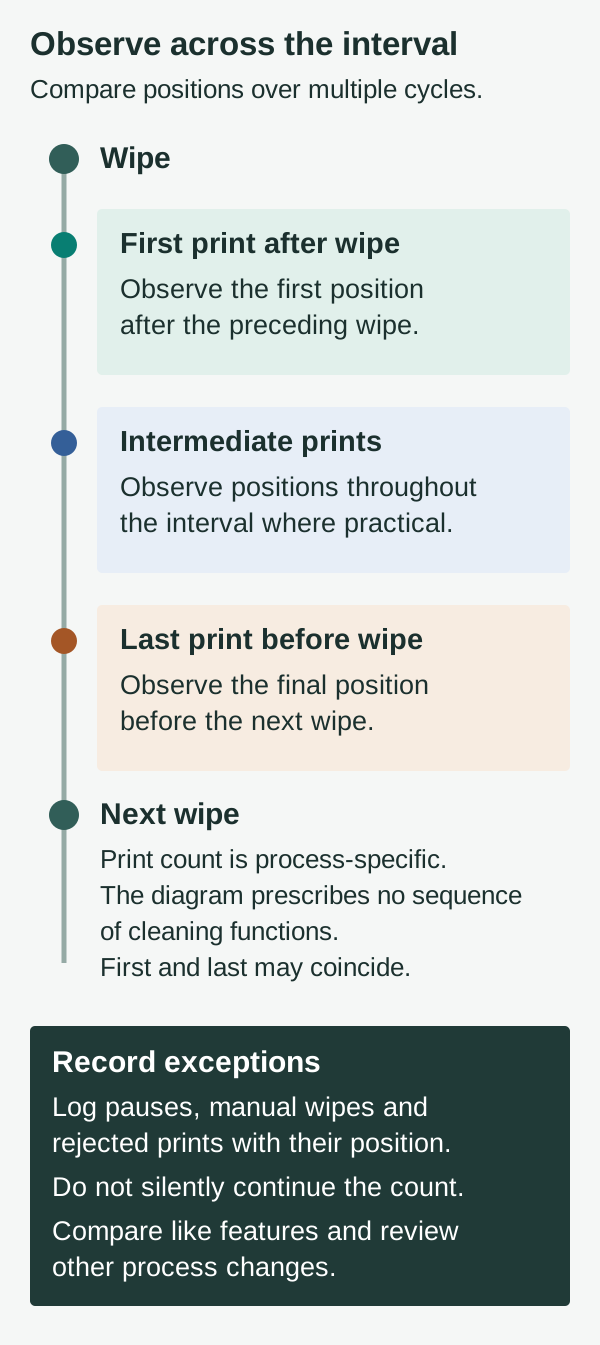
Define the interval first. For example, if a wipe occurs after the last print in a cycle, position 1 is the first print after the preceding wipe and the final position is the print immediately before the next wipe. Record exceptions, such as a manual wipe, stoppage or rejected print, rather than silently continuing the count.
Set a starting recipe. Use equipment and material instructions, engineering judgment, product risk and any relevant site experience. Choose an initial interval cautiously; it is a trial condition, not an industry limit.
Agree on evaluation criteria in advance. Define the applicable deposit and defect requirements, SPI review rules, escalation actions and trial duration. Include relevant board locations and small or otherwise sensitive apertures. Requirements must come from the product and process owners; the cleaning trial does not create them.
Collect across the interval. Capture SPI data for successive boards at known positions, including immediately before and immediately after each wipe. Where practical, inspect the full cycle rather than sampling only those two boards. Record residue observations safely at approved stops.
Examine distributions, not just averages. Review deposit volume, height and area as appropriate, plus defect calls and their locations. Look at spread, tails, outliers and recurring patterns at individual apertures. Compare like features and interval positions; a board-wide average can hide a localized problem.
Investigate the pattern before changing the recipe. If deposits deteriorate toward a wipe and recover afterward, underside contamination is a plausible contributor—not automatically the only cause. Confirm SPI setup and investigate support, gasketing, stencil condition and material delivery.
Test an alternative under controlled conditions. A shorter interval, a different pass combination or a paper-setting change may be worth evaluating. Change one main factor at a time when practical, document the others, and repeat enough cycles to understand variation. Avoid attributing a difference to wiping if paste condition, operator, board lot or another major variable changed at the same time.
Approve and monitor the chosen process. Compare the results with the criteria established before the trial. Include representative operating conditions and relevant lots or shifts in validation as appropriate to the product risk. Record the recipe, interval, inspection plan and actions for abnormal results.
A longer interval is not automatically better if its last positions show unstable deposits. A shorter interval is not automatically better if it adds unnecessary interruptions or introduces another problem. The decision is whether the complete cycle meets the agreed criteria under the documented trial conditions. Observed consistency alone does not establish measurement repeatability or process capability.
Use SPI as evidence, not assembly qualification
SPI can reveal shifts in deposited paste, but verify its program, alignment, reference data and measurement reliability before interpreting a trend. Investigate suspicious calls with the site’s approved inspection method; measurement artifacts and actual paste defects need different responses.
Compare distributions by feature and location, especially for prints immediately before and after a wipe. An improvement in SPI does not by itself establish finished-assembly yield or product qualification. Downstream inspection, test and qualification remain separate activities. For the inspection and disposition context, see solder paste inspection.
Diagnostic matrix: turn symptoms into checks
This matrix suggests investigation paths, not one-to-one diagnoses.
| Observation | First checks | Possible next action |
|---|---|---|
| Deposits become more variable toward the end of a cycle and recover after wiping | Interval-position data, underside residue, wipe execution and SPI consistency | Repeat the comparison; evaluate a controlled interval or recipe change. |
| Paste spreading or bridge calls recur in the same board region | Board support, local flatness, alignment, gasketing and actual paste condition | Correct support or alignment first; verify the effect across the cycle. |
| Low deposits recur at the same apertures, including just after a wipe | Aperture condition, stencil design, paste release and SPI setup | Inspect the stencil and print setup; do not assume more wiping will resolve it. |
| First print after a wet pass is unusual, then later prints recover | Fluid delivery, paper contact, selected pass functions and compatibility | Review the recipe and equipment instructions; check for excess fluid or residue before retesting. |
| Results shift after a paper roll change | Correct material, roll installation, tension, indexing and contact | Restore the specified setup and document the event. |
| Defects appear across multiple interval positions without a repeatable wipe-related pattern | Paste handling, print settings, board variation, stencil condition and measurement system | Investigate broader process stability rather than adjusting frequency alone. |
Contain affected product according to the established quality procedure while the cause is investigated. Do not use the matrix as authorization to release suspect boards.
A fictional paired comparison
Suppose a trial uses a six-print interval, with a wipe after each sixth print. Position 6 is immediately before a wipe; position 1 of the next interval is immediately after it. The eight pairs below compare one deposit across successive wipes, requiring prints through print 49.
These fictional readings are percentages of a nominal reference, not measurements or acceptance limits.
| Pair | Before wipe: print, position 6 | Before reading | After wipe: print, position 1 | After reading | After − before |
|---|---|---|---|---|---|
| 1 | 6 | 93% | 7 | 96% | +3 percentage points |
| 2 | 12 | 97% | 13 | 95% | −2 percentage points |
| 3 | 18 | 91% | 19 | 94% | +3 percentage points |
| 4 | 24 | 95% | 25 | 97% | +2 percentage points |
| 5 | 30 | 96% | 31 | 93% | −3 percentage points |
| 6 | 36 | 92% | 37 | 95% | +3 percentage points |
| 7 | 42 | 98% | 43 | 97% | −1 percentage point |
| 8 | 48 | 94% | 49 | 96% | +2 percentage points |
The before readings sum to 756, giving 756 ÷ 8 = 94.5%. The after readings sum to 763, giving 763 ÷ 8 = 95.375%. The difference between the means is 0.875 percentage points.
The paired differences go in both directions. This small, unrandomized fictional example does not estimate a wipe effect, causality, repeatability or capability. It does not replace intermediate-position data, a controlled comparison, measurement validity or agreed product criteria. An actual investigation would also examine other critical features, residue and competing process changes.
Separate stencil wiping from rejected-board reprinting
An underside wipe cleans the stencil, not paste already printed on a PCB. If SPI rejects a board, follow the documented disposition procedure. Depending on the product and site rules, the board may be held, cleaned and reprinted, or scrapped.
Where cleaning and reprinting are allowed, use the approved PCB-cleaning method and compatible materials. Verify that unwanted paste and cleaning residues have been removed, maintain identification and traceability, and inspect the reprint under the applicable procedure. Control any permitted reprint count and escalation requirements through the product’s own rules. An automatic stencil wipe does not make a rejected board acceptable.
NPI handoff checklist
Before transferring the process to production, agree on the information and owners needed to reproduce and monitor it:
- Product and risk: Board and panel revision, critical features, applicable acceptance criteria and required inspection coverage.
- Stencil: Identification, thickness and aperture revision, condition checks, storage and replacement or escalation criteria.
- Support and alignment: Support arrangement, board orientation, alignment references and checks for flatness and gasketing.
- Materials: Paste, wiping paper and solvent identities; relevant lot records, handling requirements and compatibility confirmations.
- Printer recipe: Print settings, wipe functions and order, interval definition, paper advance, fluid delivery and vacuum settings where applicable.
- Validation record: Trial conditions, interval-position data, before/after distributions, observations, deviations and the decision approving the recipe.
- Monitoring: SPI program and review method, sampling plan, warning or escalation rules, and responsibility for containment.
- Change control: Revalidation triggers for changes to boards, stencil, support, paste, paper, solvent, equipment or recipe.
- Rejected boards: Disposition authority, permitted cleaning and reprint procedure, inspection and traceability requirements.
- Supplier communication: Open questions, required process documentation and the contact responsible for resolving exceptions.
For a PCBA project involving SMT assembly, include the board and stencil requirements, assembly files, quantities and inspection needs in your quote request. Discuss the required process controls and records for the specific build.
Sources and scope
- ITW EAE, Understanding the Cleaning Process for Automatic Stencil Printers: vendor guidance on wipe functions and using observations or SPI to establish a starting frequency. Its sequence, material and chemistry advice is not universal.
- Indium, Printer Process Set-up: vendor guidance on process-specific settings and solvent-paste compatibility, not proof of one optimum.
- MicroCare, Stencil Wiping Fabric Improves Stencil Printer Through-Put: vendor-involved laboratory and field cases. Material- and site-specific results are not general guarantees.
- Circuits Assembly, Screen Printing Hacks: Cleaning Small PCBs: an equipment-company engineer’s customer case, not proof of a generally preferred sequence or solvent.
FAQ
How often should an SMT stencil underside be wiped?
Set an initial interval for the specific product and process, then validate it using residue observations and SPI data across repeated wipe cycles. There is no universal boards-per-wipe setting.
Is a wet pass always necessary?
No. The need for a wet pass depends on the contamination, materials, equipment and validated result. Confirm compatibility and fluid-delivery settings before using one.
Does vacuum cleaning guarantee clear apertures?
No. Vacuum can help remove contamination, but its effect depends on the machine, contact, paper and stencil condition. Persistent aperture-related defects require investigation.
What should engineers compare before and after a wipe?
Compare like SPI features immediately before and after each wipe, including distribution spread, outliers and locations—not just the mean. Also inspect intermediate interval positions and record other process changes.
Can a rejected PCB be reprinted after an underside wipe?
Not merely because the stencil was wiped. The PCB needs its own approved disposition; if cleaning and reprinting are permitted, follow the documented cleaning, traceability and reinspection controls.