
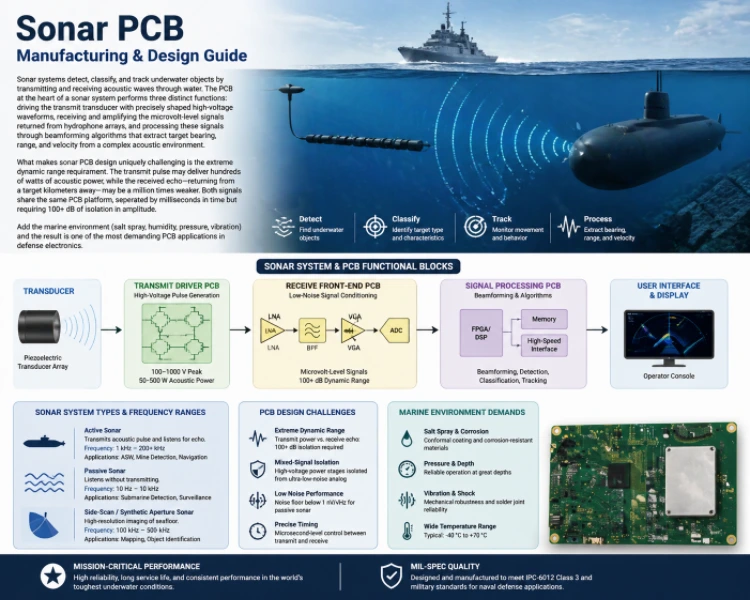
The global naval sonar market exceeded $5.1 billion in 2024, with anti-submarine warfare modernization driving demand across NATO navies. Sonar systems detect, classify, and track underwater objects by transmitting and receiving acoustic waves. The PCB performs three distinct functions: driving the transmit transducer with precisely shaped high-voltage waveforms, receiving and amplifying microvolt-level hydrophone returns, and processing these signals through beamforming algorithms that extract target bearing, range, and velocity from a complex acoustic environment.
Submarines and surface warships operated by the United States Navy, Royal Navy, Royal Canadian Navy, Royal Australian Navy, and Norwegian Navy rely on sonar PCBs meeting the operational demands of North Atlantic, Pacific, and Arctic waters. Commercial marine sonar for fishing fleets in Norway, Iceland, and Canada imposes different but equally rigorous environmental requirements.
What makes sonar PCB design uniquely challenging is extreme dynamic range. The transmit pulse delivers hundreds of watts of acoustic power, while the received echo may be a million times weaker. Both signals share the same PCB platform, separated by milliseconds in time but requiring 100+ dB of isolation in amplitude. Combined with the marine environment—salt spray, humidity, pressure, vibration—sonar is one of the most demanding PCB applications in defense electronics.
HILPCB Manufacturing Capability: We fabricate sonar PCBs with mixed-signal isolation exceeding 100 dB, heavy copper power stages for transmit drivers, conformal coating for marine environments, and IPC-6012 Class 3 qualification for naval defense programs.
In This Guide
- Transmit Driver PCB: High-Voltage Pulse Generation
- Receive Channel PCB: Low-Noise Hydrophone Front-End
- Beamforming and Signal Processing Boards
- Material Selection and Marine Environment Protection
- DFM, Production Testing, and Quality Assurance
- HILPCB Sonar PCB Manufacturing
Transmit Driver PCB: High-Voltage Pulse Generation
Active sonar transmit drivers generate precisely shaped high-voltage pulses — 100–1000 V peak delivering 50–500 W acoustic power through piezoelectric or magnetostrictive transducers. The PCB must handle these power levels while preventing transmit energy from coupling into the sensitive receive electronics sharing the same enclosure.At HILPCB, our sonar transmit board fabrication addresses the high-voltage isolation, heavy copper current handling, and thermal management that reliable sonar transmission demands in continuous naval operation.
Transmit Driver Design
- High-Voltage Switching: MOSFET or IGBT H-bridge circuits generating shaped pulses with rise times of 1–10 μs. Heavy copper planes (3–4 oz) on multilayer constructions carry the pulsed current without excessive resistive heating or voltage drop.
- Transducer Matching: Output matching networks tuned to the transducer impedance at the operating frequency (1–200 kHz). Impedance-controlled traces with low-ESR capacitors and precision inductors in the matching network maintain acoustic output consistency.
- Transmit/Receive Isolation: Physical separation between transmit driver and receive preamplifier sections with ground plane partitioning and filtered power connections maintaining >100 dB isolation during the receive window.
- Power Supply Sequencing: High-voltage rail sequencing prevents transient surges that could damage transducers during power-up/down — particularly critical for hull-mounted arrays where transducer replacement requires dry-docking.
Validated Transmit Performance
Every sonar transmit board undergoes output waveform verification, impedance matching validation, and isolation testing confirming that transmit-to-receive leakage stays below the specified -100 dB threshold across the operating frequency range.
Receive Channel PCB: Low-Noise Hydrophone Front-End
Passive and active sonar receive channels must detect acoustic signals at -80 to -120 dB below the transmit level — requiring preamplifier noise floors below 1 nV/√Hz and multi-channel arrays processing 32–256 hydrophone elements simultaneously on a single board.At HILPCB, our receive channel board designs achieve the noise floors and channel matching that towed array and hull-mounted sonar systems demand — through precision analog layout, dedicated ground architectures, and controlled fabrication cleanliness.
Receive Channel Architecture
- Low-Noise Preamplifiers: Input-referred noise below 1 nV/√Hz with guard traces, stripline shielding on inner layers, and dedicated analog ground planes. Component selection specifies low-noise op-amps (AD797, OPA1612) with thermal symmetry across differential inputs.
- Time-Variable Gain (TVG): Programmable gain amplifiers increasing sensitivity over time after each transmit pulse to compensate for propagation loss — gain ramps from 0 dB to 80+ dB over 0.1–10 seconds depending on range.
- Multi-Channel ADC: 24-bit sigma-delta ADCs (48–200 kHz sampling per channel) with simultaneous sampling across all channels — no multiplexing, which introduces inter-channel phase errors degrading beamforming accuracy.
- Channel Matching: ±0.1% resistors and ±1% capacitors across all channels with matched trace lengths maintaining <0.5° phase matching at the maximum operating frequency.
Beamforming and Signal Processing Boards
Sonar beamforming combines outputs from multiple hydrophone elements to form directional receive beams — rejecting noise from unwanted directions while amplifying signals from the target bearing. The processing board performs this computation in real-time, typically on high-performance FPGAs, managing hundreds of channels with microsecond timing precision.At HILPCB, our beamforming board fabrication delivers the HDI density, controlled impedance, and thermal management that FPGA-intensive sonar signal processors require.
Processing Board Design
- FPGA Platform: Xilinx Zynq UltraScale+ or Intel Stratix 10 on 14–20 layer boards with HDI escape routing for 1500+ ball BGAs at 0.8 mm pitch.
- High-Speed Data Interfaces: Multi-channel ADC data arriving via LVDS or JESD204B from the receive board, routed on high-speed controlled-impedance inner layers with matched lengths.
- Memory Bandwidth: DDR4 memory banks supporting the data throughput requirements of real-time beamforming — multiple channels of matched-length, impedance-controlled routing.
- Display and Communication: Processed sonar imagery output to operator displays and combat management systems via Ethernet, fiber optic, or MIL-STD-1553B interfaces.
Material Selection and Marine Environment Protection
Sonar electronics operate in the harshest environment in defense electronics — naval platforms exposed to salt spray, condensation, vibration from engines and sea state, and temperature cycling from tropical to arctic waters. Material selection and environmental protection determine whether sonar boards survive 10+ year naval service life.At HILPCB, our marine-grade fabrication uses materials and processes validated for the specific environmental stresses of naval surface ship, submarine, and sonobuoy applications.
Marine Protection Engineering
- Board Material: High-Tg FR-4 (Tg ≥170°C) with ENIG surface finish resisting galvanic corrosion from combined salt and humidity exposure. Polyimide substrates for boards subjected to sustained high-temperature operation near engine rooms.
- Conformal Coating: Silicone-based coating per IPC-CC-830 rated for continuous 95% RH and salt fog per MIL-STD-810H. Masking protects connectors, test points, and antenna interfaces.
- Vibration Endurance: Underfill on critical BGAs, corner staking on large passives, and component orientation aligned with the primary vibration axis for hull-mounted installations.
- Pressure Qualification: Sonar electronics in submarine towed arrays may experience hydrostatic pressure — board and conformal coating validated for pressure cycling at rated operating depth.
DFM, Production Testing, and Quality Assurance
Sonar PCBs undergo testing that verifies both electrical performance and environmental survival — because a sonar system failure at sea may not be repairable until the vessel returns to port.At HILPCB, our sonar production quality program addresses the specific test requirements of naval electronics — from noise floor verification through environmental qualification.
Testing and Quality Framework
- Noise Floor Verification: Reference signal injection testing on every receive board confirming preamplifier noise below 1 nV/√Hz and channel-to-channel matching within specification.
- Isolation Testing: Transmit-to-receive isolation verified at >100 dB across the operating frequency range on every assembled unit.
- Environmental Qualification: Temperature cycling (-40°C to +71°C, 500+ cycles), vibration (5–500 Hz, 3G), and salt fog (per MIL-STD-810H) on representative samples from each production lot.
- SMT Assembly: J-STD-001 Class 3 soldering with 100% AOI and X-ray inspection on BGA components. From prototype through production volume, our process maintains the analog precision and mechanical robustness that naval sonar demands.
HILPCB Sonar and Naval Electronics Programs
Since 2016, HILPCB has delivered sonar and underwater acoustic electronics programs for naval defense contractors and commercial marine companies across the United States, United Kingdom, Canada, France, Norway, and Australia.
Our capabilities include heavy copper transmit driver boards with high-voltage isolation, ultra-low-noise receive channel arrays with >100 dB isolation, HDI beamforming processor boards for FPGA-intensive signal processing, marine-grade materials and conformal coating for 10+ year naval service life, rigid-flex construction for compact sonobuoy and torpedo electronics, and IPC-6012 Class 3 fabrication with full material traceability.
Sonar PCB FAQ
How do sonar PCBs isolate the high-voltage transmit pulse from the sensitive receiver?
To achieve >100 dB of isolation between the high-power transmit pulse and the microvolt-level receive signals, the PCB employs strict physical separation, partitioned ground planes, and dedicated filtered power supplies. Without this, the transmit pulse would blind or destroy the sensitive receiver preamplifiers.
Why is simultaneous sampling critical for multi-channel hydrophone arrays?
Beamforming relies on measuring minute phase differences between acoustic signals arriving at different hydrophone elements. If the ADC uses multiplexing instead of simultaneous sampling, it introduces artificial timing skew (phase errors) between channels, which severely degrades the sonar's ability to accurately determine target bearing.
How are sonar PCBs protected against the marine environment?
Naval sonar boards face extreme humidity, salt fog, and temperature cycling. Protection involves using high-Tg FR-4 or polyimide substrates, applying military-grade silicone conformal coating (IPC-CC-830), and using ENIG surface finishes to prevent galvanic corrosion. Components are also staked and underfilled to survive intense vibration.