
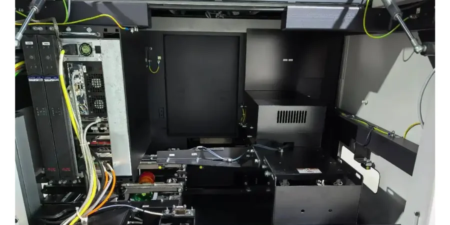
SPI, AOI and X-ray inspection are complementary process controls for measuring solder paste, checking visible assembly features and evaluating hidden structures. For ADAS and EV power electronics, the inspection plan must connect each safety or reliability risk to a defined method, coverage level, acceptance rule and reaction plan.
Key Takeaways
- SPI controls the printing process before components and reflow can turn a paste defect into a costly assembly defect.
- AOI is strongest on visible component and solder features; it cannot prove hidden-joint integrity, component value or electrical function.
- 2D X-ray, laminography and 3D CT provide different evidence. Select the technique, view and resolution from the defect being sought.
- Do not apply one universal voiding percentage to every BGA, QFN, thermal pad or power device. Release package-specific criteria and measurement rules.
- Inspection data creates value only when it is revision-controlled, tied to the board serial number and used to correct the upstream process.
Table of Contents
- What does each inspection method prove?
- How should ADAS assemblies be inspected?
- How should EV power assemblies be inspected?
- Which method covers each defect?
- How should inspection be released from NPI to volume?
- How should false calls and escapes be controlled?
- What must traceability retain?
- Automotive inspection RFQ checklist
- Frequently asked questions
What Does Each Inspection Method Prove?
An inspection gate should answer a specific manufacturing question. “100% AOI” is not a complete quality plan because it says nothing about the program revision, package visibility, defect library, acceptance criteria or escalation path.
| Method | Best evidence | Important limits |
|---|---|---|
| 3D SPI | paste area, height, volume, offset, shape and bridging risk after print | cannot verify placement, reflowed joints or electrical function |
| 2D/3D AOI | visible presence, polarity, orientation, position, leads, fillets, bridges and surface anomalies | cannot see most joints under BGA/LGA/BTC packages or identify every visually identical wrong value |
| 2D X-ray | rapid projection view of hidden joints, bridges, gross opens, voids and solder distribution | overlapping structures can obscure defects; a projection does not localize every feature in depth |
| Laminography/3D CT | reconstructed slices for concealed or overlapping structures | cycle time, programming, resolution and interpretation must fit production needs |
| ICT/boundary scan | accessible opens, shorts, values and digital interconnects | requires electrical access, coverage analysis and controlled test software |
| Functional test | defined powered behavior and interfaces | may not reveal latent workmanship defects or isolate root cause |
SPI and AOI become process-control tools when quantitative results are trended by printer, stencil, aperture, placement head, feeder, nozzle, component and reflow recipe. X-ray becomes more useful when each image is tied to the exact package, board revision, view, algorithm and acceptance rule.
How Should ADAS Assemblies Be Inspected?
ADAS domain controllers combine fine-pitch SoCs, memories, PMICs, serializers, Ethernet devices and many decoupling components. The primary inspection risks are dense hidden joints, polarity/placement errors, paste transfer on fine apertures and electrically untestable interconnects.
Use SPI to stabilize paste transfer before reflow. Volume alone is not enough; review offset, shape, bridging and pad-to-pad balance for the package. Use AOI after placement or reflow to check visible orientation, missing parts, lifted leads and exposed solder. Assign X-ray views to BGAs, LGAs, QFNs and other bottom-termination components whose joints are not optically accessible.
High-speed physical-layer performance needs separate evidence. AOI on an assembled board does not prove buried differential-pair geometry, and X-ray does not prove impedance. Use fabrication metrology, microsections, impedance coupons and TDR for a high-speed PCB; use electrical and functional tests for GMSL, FPD-Link, automotive Ethernet or other released interfaces.
Boundary scan or JTAG can extend interconnect coverage around compatible SoCs, FPGAs and memories when physical probes cannot reach the nets. Coverage depends on the actual device models, chain architecture, constraints and test program—it is not automatic because a JTAG header exists.
How Should EV Power Assemblies Be Inspected?
Inverters, onboard chargers, DC/DC converters and BMS assemblies add high-current joints, thermal interfaces, press-fit or through-hole connections, power semiconductors and high-voltage separation. Structural inspection must be paired with electrical safety and thermal verification.
| Risk | Structural evidence | Additional evidence |
|---|---|---|
| thermal-pad voiding | defined X-ray/CT view and package-specific calculation | thermal characterization under representative power and cooling |
| insufficient THT/THR solder | side view, X-ray/CT or destructive cross-section as specified | electrical resistance and mechanical/process validation |
| heavy-component misalignment | AOI, dimensional inspection and fixture check | vibration/mechanical qualification |
| creepage/clearance obstruction | optical/dimensional inspection and controlled cleanliness process | dielectric withstand or insulation-resistance test where specified |
| power-device joint degradation | X-ray/CT baseline and process monitoring | thermal cycling, power cycling or other product qualification |
| wrong or damaged power component | AOI/marking verification and traceability | ICT/FCT and parameter test |
There is no universally correct “below 25%” void criterion for all automotive joints. Acceptance can depend on component construction, void location and distribution, customer drawing, process standard and thermal design. Define the calculation method, region of interest, image conditions and disposition authority before production.
X-ray attenuation does not directly prove that a high-voltage isolation zone is free of ionic residue or that creepage is electrically adequate. Use cleanliness controls and the specified insulation or dielectric test. Likewise, a void percentage does not by itself prove junction temperature or service life.
Which Method Covers Each Defect?
This matrix is a practical release asset: it maps the defect to its earliest effective control, confirmation method and escalation rule.
| Defect/risk | Earliest control | Confirmation | Escalate when |
|---|---|---|---|
| insufficient/excess paste | 3D SPI | post-reflow AOI/X-ray on affected package | trend crosses the approved process limit or repeats by aperture |
| paste offset/bridging | 3D SPI | AOI/X-ray after reflow | pad-to-pad imbalance or bridge risk repeats |
| missing, rotated or wrong-polarity part | placement verification/AOI | operator verification plus ICT/FCT where relevant | library, feeder or BOM mapping is suspect |
| visible open, bridge or lifted lead | AOI | microscope or electrical test | same package/line position repeats |
| hidden BGA/LGA/BTC open or bridge | X-ray/CT | electrical test or destructive analysis if ambiguous | projection overlap prevents confident disposition |
| head-in-pillow | suitable angled X-ray/CT and process review | cross-section when required for root cause | paste, component warpage or profile trend is unresolved |
| thermal-pad voiding | defined X-ray/CT measurement | thermal test/process qualification | limit, distribution or measurement repeatability fails |
| wrong passive value | material control and placement traceability | ICT/FCT or component measurement | vision cannot distinguish the marking/value |
| high-speed link failure | fabrication controls and assembly inspection | TDR/VNA/interface functional test as applicable | structural inspection passes but link margin fails |
| high-voltage insulation risk | dimensional and cleanliness controls | hi-pot/insulation resistance per released plan | contamination, damage or failed electrical result occurs |
The earliest control is usually the cheapest place to act. A paste-volume trend should trigger stencil, squeegee, support, paste or printer review before boards proceed, not merely create a post-reflow repair queue.
How Should Inspection Be Released from NPI to Volume?
EVT, DVT and PVT labels vary by company, so release objective evidence rather than relying on the phase name.
- Coverage design: classify components and joints by visibility, product risk and available electrical test coverage.
- Program creation: load the correct BOM, CAD, Gerber, polarity, package and panel data; control all inspection and test revisions.
- First-article correlation: deliberately review representative good and known-defect examples where practical; confirm measurement repeatability and operator disposition.
- Process-window validation: correlate paste, placement, reflow and X-ray results to cross-sections, electrical tests or reliability work when the risk justifies it.
- Volume release: define 100% versus sampling coverage, stop/hold rules, reinspection, rework limits and authorization for deviation.
- Change response: repeat the affected validation after stencil, paste, package, supplier, program, equipment, fixture, reflow or design changes.
An FAI or PPAP package should identify the approved revision, actual materials, process flow, measurement results, exceptions and customer approvals. A report with screenshots but no acceptance criteria or revision identity is not a robust release record.
How Should False Calls and Escapes Be Controlled?
False calls consume verification time and can train operators to dismiss alarms; escapes create false confidence. Both are inspection-system performance measures.
Set up an attribute agreement or measurement-system study appropriate to the output. Track false calls, verified defects, escapes and “cannot judge” results by package and defect class. Do not tune a program merely to reduce alarms: preserve known-defect sensitivity, require reason codes for overrides and route uncertain cases to a higher-information method such as angled X-ray, CT, microscope or electrical test.
The reaction plan should state who stops the line, what inventory is quarantined, how the suspect window is determined, which boards are reinspected and what evidence permits restart. Trend data without a reaction threshold is reporting, not control.
What Must Traceability Retain?
For each serialized assembly, retain the product and panel revision, material lots, stencil and paste, machine/program revisions, placement source, reflow recipe, inspection result, verified defect, rework history, electrical-test result and disposition according to the contracted retention policy.
Connect records through MES or another controlled system, but validate the data relationships. A barcode is not traceability if the inspection image, component lot and test result cannot be retrieved or if a rerun silently overwrites the original failure.
IPC-1782 can inform electronics traceability planning, and IPC-CFX or other interfaces can move production data between equipment and factory systems. The OEM and supplier still must define required data, retention, access, cybersecurity and change control.
Automotive Inspection RFQ Checklist
Product and risk
- assembly drawing, BOM/AVL, centroid, Gerber/ODB++ or IPC-2581, panel and revision;
- product function, automotive use, safety/reliability risks and customer-specific requirements;
- package list highlighting BGA/LGA/QFN/BTC, power devices, press-fit, THT/THR and conformal coating.
Inspection scope
- SPI/AOI/X-ray stage, 100% or sampling coverage and package/feature coverage map;
- 2D, angled, laminography or CT method; views, resolution, region of interest and measurement rule;
- workmanship class/addendum, void criteria, golden samples and deviation authority;
- program validation, false-call/escape monitoring, operator verification and escalation rules.
Electrical and release evidence
- bare-board test/TDR, boundary scan, ICT, FCT, programming and high-voltage test coverage;
- first-article/PPAP deliverables, cross-section or reliability correlation and customer approvals;
- serialization, material/process records, image/raw-data retention, rework history and change notification;
- prototype, qualification, monthly/lifetime volume, takt-time and report-format requirements.
HILPCB can review package visibility, inspection coverage, assembly data and test boundaries for small-batch assembly or turnkey PCB assembly. Product safety concept, functional-safety analysis, automotive qualification, electrical/thermal limits and final vehicle acceptance remain with the responsible product organization unless explicitly assigned and verified.
Reference Standards and Specifications
- IPC J-STD-001 — IPC
- IPC-A-610 — IPC
- Automotive Addendum to IPC J-STD-001 and IPC-A-610 — IPC
- IPC-7093 — IPC
- IPC-7095 — IPC
- IPC-7525 — IPC
- IPC-1782 — IPC
- IATF 16949 — International Automotive Task Force
- ISO 26262 — International Organization for Standardization
Confirm current revisions, product class, customer-specific requirements and the contractually applicable automotive addenda before release.
Frequently Asked Questions
Can AOI replace X-ray for an automotive BGA?
No. AOI can inspect visible package and board features, but most BGA joints are hidden. Use a qualified X-ray/CT method plus electrical coverage appropriate to the package and risk.
Does 100% X-ray guarantee zero hidden-joint defects?
No. Coverage also depends on view, resolution, overlap, program limits, calibration and defect detectability. Some ambiguous conditions require CT, electrical test or destructive analysis.
What is the difference between SPI and AOI?
SPI measures printed solder paste before placement. AOI checks visible components and solder features before or after reflow. They control different process stages and should not be treated as substitutes.
What voiding limit should be used for EV power devices?
Use the released component, customer and design criteria, including void location and distribution where relevant. Validate that the selected limit supports thermal and reliability requirements instead of copying one generic percentage.
Is inspection enough for ISO 26262 compliance?
No. Inspection provides manufacturing evidence within a broader safety lifecycle. Functional-safety responsibilities, analyses, requirements, verification and confirmation measures extend beyond PCB assembly inspection.
Make Inspection a Controlled Feedback System
The best automotive inspection plan catches defects early, exposes blind spots and drives corrective action before escape risk grows. Define the evidence chain from solder paste through radiography and electrical test, then preserve every result against the exact board and process revision.