
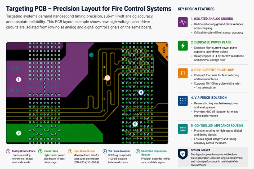
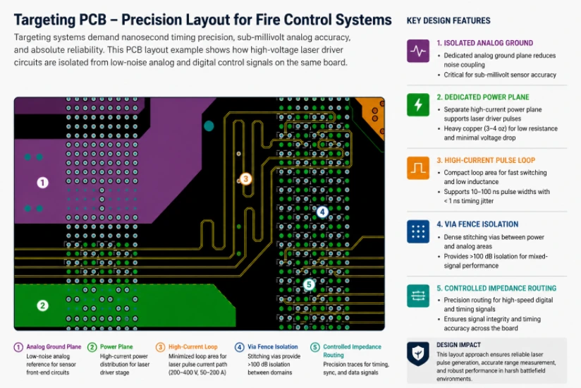
The global fire control system market reached $6.8 billion in 2024, with guided munition programs and tank modernization driving demand across NATO defense budgets. Targeting systems convert sensor data — laser rangefinder returns, optical tracker measurements, GPS coordinates, and inertial navigation outputs — into precise firing solutions for weapons platforms. The PCBs within these systems must deliver nanosecond timing for laser pulse generation, sub-millivolt analog accuracy for sensor conditioning, real-time ballistic computation, and absolute reliability under battlefield conditions.
Fire control systems are critical to defense forces in the United States, Germany, the United Kingdom, France, Canada, and Australia. Whether the platform is an M1 Abrams (US Army), Leopard 2 (Bundeswehr), Challenger 3 (British Army), or a naval vessel in the North Sea, the targeting PCB must deliver accurate firing solutions in extreme environmental conditions — from desert heat to arctic cold.
A targeting system failure means a missed target or unintended engagement. There is no tolerance for intermittent connections, impedance drift, or thermal-induced timing errors. Defense integrators partner with HILPCB for targeting PCBs because our Class 3 fabrication quality, controlled impedance precision, and full material traceability meet defense procurement documentation requirements.
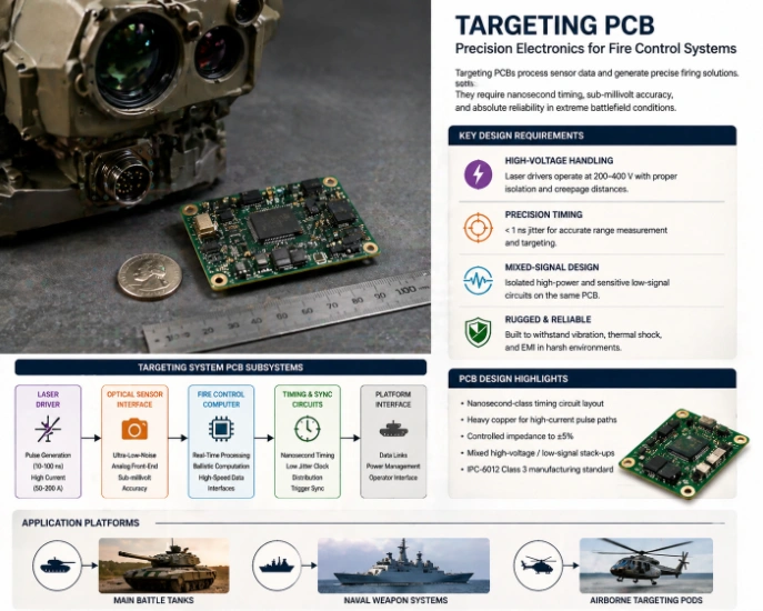
HILPCB Manufacturing Capability: We fabricate targeting system PCBs with nanosecond-class timing layout, mixed high-voltage/low-signal stack-ups, controlled impedance to ±5%, and IPC-6012 Class 3 qualification for ground, naval, and airborne fire control programs.
In This Guide
- Laser Rangefinder and Designator Driver PCB Design
- Optical Sensor Interface and Tracking Electronics
- Fire Control Computer Board Architecture
- Precision Timing and Environmental Qualification
- DFM, Testing, and Production Quality
- HILPCB Targeting PCB Capabilities
Laser Rangefinder and Designator Driver PCB Design
Laser rangefinders measure target distance by timing a pulsed laser round-trip; laser designators illuminate targets for guided munitions. Both require PCB circuits that switch high-voltage, high-current pulses with nanosecond precision while coexisting with sensitive timing measurement electronics on the same board.At HILPCB, our laser driver board fabrication addresses the high-voltage isolation, heavy copper pulse paths, and nanosecond timing layout that defense-grade laser systems demand.
Laser Driver PCB Engineering
- Pulsed Current Paths: Flash-lamp or diode-pumped lasers draw 50–200 A peak for 5–30 ns duration. Heavy copper inner layers (3–4 oz) with minimized loop inductance deliver clean current pulses without voltage droop.
- High-Voltage Isolation: Capacitor charging circuits at 300–1000 V require creepage distances per IPC-2221 with conformal coating reducing clearance requirements. Multilayer construction routes high-voltage on inner layers shielded by ground planes.
- Timing Measurement: Time-to-digital converters measuring laser round-trip with ±0.5 ns precision (±0.075 m range accuracy) require matched trace lengths and low-jitter clock distribution.
- Eye-Safe Control: Laser safety interlock circuits with hardware redundancy preventing unauthorized emission — critical for systems used in training and populated areas.
Validated Laser Performance
Every laser driver board undergoes pulse shape verification, timing accuracy validation, and high-voltage insulation testing — ensuring that production boards match the prototype performance that qualified the weapon system.
Optical Sensor Interface and Tracking Electronics
Targeting systems use EO/IR cameras and tracking sensors to acquire, identify, and follow targets. The sensor interface PCB provides the precision analog conditioning that determines whether the tracker can maintain lock on a moving target under battlefield conditions.At HILPCB, our sensor interface designs for targeting systems achieve the low-noise performance and high-speed video processing that real-time target tracking demands — on compact boards fitting within weapon sight enclosures.
Sensor Interface Architecture
- EO/IR Camera Interface: CMOS/CCD bias regulation with <200 μV ripple, LVDS or MIPI CSI video output at 1–4 Gbps per lane, and lens motor control with isolated drive circuits.
- Tracking Processor: FPGA or DSP performing centroid calculation, correlation tracking, and prediction algorithms at frame rate (30–120 Hz). HDI construction for FPGA BGA escape routing on compact boards.
- Target Identification: Image processing for automatic target recognition (ATR) requiring DDR4 memory banks for frame buffer and template storage — controlled-impedance routing on dedicated signal layers.
- Display Interface: Reticle overlay generation and video output to the gunner's eyepiece display with low-latency (<1 frame) processing to maintain aiming accuracy.
Fire Control Computer Board Architecture
The fire control computer integrates all sensor inputs — range, bearing, target velocity, wind, ammunition type, and platform motion — to compute firing solutions in real-time. The PCB carries a high-performance processor with multiple sensor interfaces, ballistic computation algorithms, and communication links to the weapons platform.At HILPCB, our fire control computer board fabrication delivers the processing density, signal integrity, and environmental robustness that real-time ballistic computation demands across operating temperature extremes.
Fire Control Board Design
- Processing Platform: ARM-based or x86 embedded processors with real-time operating system support. 10–16 layer boards with controlled impedance for DDR4 and PCIe interfaces.
- Sensor Fusion Input: Simultaneous interfaces to laser rangefinder (serial), tracker (video), GPS receiver, IMU (SPI), and wind sensor — each requiring appropriate isolation and timing.
- Communication Links: MIL-STD-1553B, CAN bus, or Ethernet interfaces to the weapons platform fire control network — with galvanic isolation on data links exposed to external cabling.
- FR-4 Material with Tg ≥170°C ensuring reliable operation across the -46°C to +71°C ground vehicle temperature range with solder joints validated for 1000+ thermal cycles.
Precision Timing and Environmental Qualification
Targeting systems require nanosecond-precision timing synchronized across laser, tracker, and computer subsystems — and must maintain this precision across the full military environmental envelope. Timing errors translate directly to range measurement errors and miss distance.At HILPCB, our timing circuit layout and environmental qualification testing ensure that targeting boards maintain specification accuracy from -46°C to +71°C under vibration, shock, and EMI conditions.
Timing and Environment
- Clock Distribution: Low-jitter TCXO reference distributed to all subsystems through impedance-matched stripline traces with <1 ps RMS jitter contribution.
- Timing Calibration: Per-board delay measurement and compensation coefficients stored in non-volatile memory — accounting for trace length variation and temperature-dependent propagation delay.
- MIL-STD-810H Qualification: Temperature cycling, shock (40G), vibration (5–2000 Hz at 5G RMS), sand/dust, and humidity testing on representative production samples.
- MIL-STD-461G EMI/EMC: Conducted and radiated emission/susceptibility testing confirming electromagnetic compatibility with co-located vehicle electronics and communication systems.
DFM, Testing, and Production Quality
Targeting PCBs undergo testing that goes beyond standard electrical verification — because these boards must function correctly the first time, every time, in conditions where re-test is not an option.At HILPCB, our targeting PCB quality program addresses defense procurement requirements through comprehensive testing, traceability, and process documentation.
Quality Framework
- Production Testing: 100% electrical test, controlled-impedance verification, functional test with sensor simulation, and timing accuracy validation on every board.
- SMT Assembly: J-STD-001 Class 3 with 100% AOI, X-ray on BGA components, and reflow profile documentation for traceability.
- Burn-In: 72-hour powered operation at elevated temperature for defense program boards — stressing infant-mortality failures before delivery.
- Prototype Validation: First-article builds for qualification testing before production commitment, with formal inspection documentation per AS9102.
Why Defense Integrators Partner with HILPCB for Targeting Electronics
HILPCB fabricates targeting system PCBs for defense contractors and weapons system integrators across the United States, United Kingdom, Germany, France, Canada, and Australia.
Our capabilities include heavy copper laser driver boards with high-voltage isolation, HDI sensor interface boards for compact weapon sight enclosures, fire control computer boards with multi-interface sensor fusion, rigid-flex construction for gimbal-mounted and turret-installed targeting systems, MIL-STD-810H/461G environmental qualification support, and IPC-6012 Class 3 fabrication with full material traceability for defense procurement.
Targeting PCB FAQ
Why is nanosecond timing precision critical for laser rangefinder PCBs?
A laser rangefinder calculates distance based on the round-trip time of a light pulse. A timing jitter of just 1 nanosecond translates to a 15-centimeter range error. The PCB must distribute ultra-low-jitter clocks (<1 ps RMS) via impedance-matched traces to ensure absolute ballistic accuracy.
How do you handle 200A laser pulses on a standard-sized PCB?
Laser designators draw massive, instantaneous current spikes (e.g., 200A for 20 ns). To prevent catastrophic voltage droop and electromagnetic interference, the board utilizes 3-4 oz heavy copper inner layers with minimized loop inductance, supported by specialized high-voltage isolation techniques.
What environmental tests are required for military fire control PCBs?
Targeting electronics must operate flawlessly from arctic cold to desert heat (-46°C to +71°C) while enduring the shock of weapons fire. We qualify boards to MIL-STD-810H standards, subjecting them to severe temperature cycling, 40G mechanical shock, 5G RMS vibration, and MIL-STD-461G EMI/EMC compliance.