
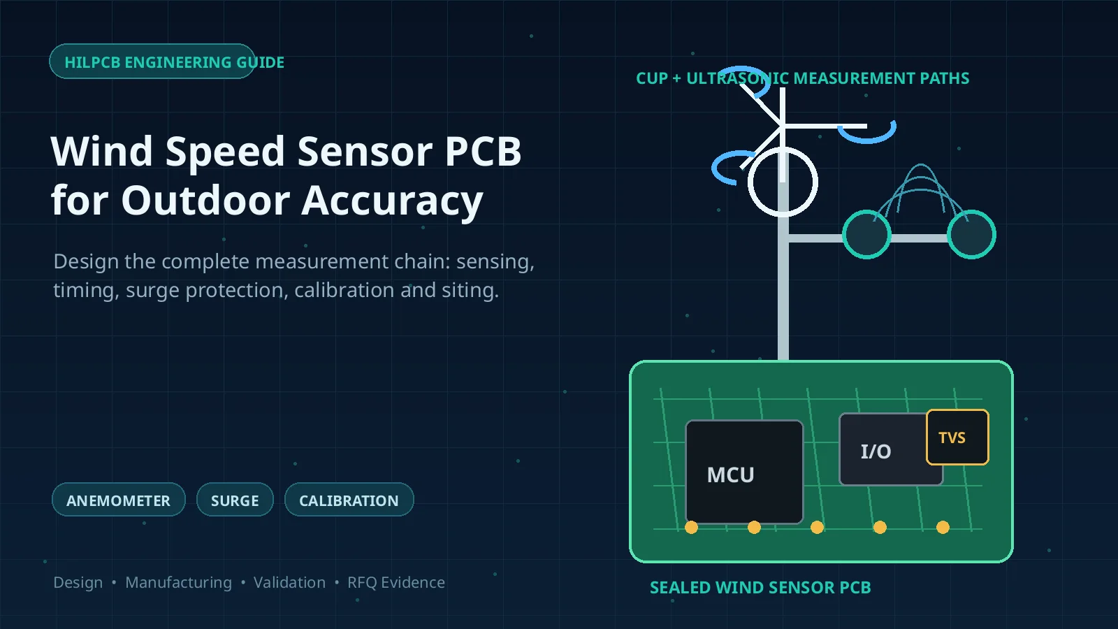
A wind speed sensor PCB converts a mechanical, acoustic, or thermal sensing response into timestamped wind data that a logger, controller, or weather station can use. The board can protect and process the signal, but measurement accuracy also depends on the sensing head, mounting, airflow distortion, calibration, enclosure, cable system, firmware, and site.
This guide helps engineers and buyers specify outdoor anemometers and weather-station nodes from release evidence instead of an undefined “outdoor grade” label.
Key Takeaways
- Cup, propeller, ultrasonic, and thermal anemometers create different signal-chain, power, maintenance, and calibration risks; one generic “sensor PCB” specification cannot cover them all.
- Ultrasonic time-of-flight electronics need controlled timing, low-noise receive paths, and careful transducer switching, but they do not automatically require controlled-impedance traces or RF laminate.
- IP ratings apply to the tested enclosure or complete product configuration. A bare PCB, solder mask, surface finish, or conformal coating does not establish IP67 or IP68.
- TVS diodes, GDTs, and MOVs are components within a surge strategy. Lightning resilience also depends on bonding, grounding, cable entry, shielding, routing, separation, and system-level tests.
- High-Tg laminate does not prove low-temperature toughness, thermal conductivity, or a finished product's operating range. Select materials from the actual temperature, moisture, mechanical, insulation, and fabrication requirements.
- Calibration evidence should identify the sensor, method, range, fitted relationship, uncertainty, environmental conditions, and traceability. A fan check proves function, not measurement accuracy.
- A useful RFQ separates PCB fabrication and PCBA evidence from sensing-head calibration, enclosure ingress, environmental qualification, installation, and field-maintenance responsibilities.
Contents
- How Do Wind Sensor Types Change the PCB?
- What Requirements Should Be Frozen Before Layout?
- How Should the Signal Chain Be Designed?
- How Should Power and Communications Work at a Remote Site?
- How Do You Protect Outdoor Wind Electronics?
- What Does Real Lightning and Surge Protection Require?
- How Should Measurement Uncertainty and Release Evidence Be Managed?
- How Should Calibration and Maintenance Be Planned?
- How Do You Diagnose Wind Sensor Failures?
- What Should Be Included in a Wind Sensor PCB RFQ?
How Do Wind Sensor Types Change the PCB?
The measurement principle determines what the electronics must preserve. Buyers should select the sensing architecture from the wind range, response, direction needs, icing exposure, maintenance access, power budget, and required calibration evidence before optimizing the board.
| Sensor type | Measurement principle | Main electronic functions | Dominant non-PCB risks | Typical maintenance concern |
|---|---|---|---|---|
| Cup anemometer | Wind rotates cups; speed is inferred from rotation rate | Hall, reed, magnetic, or optical input; pulse shaping; timer capture; frequency conversion | Cup geometry, starting behavior, overspeed response, bearing friction, mast and boom flow distortion | Bearing wear, contamination, damaged cups, changed rotor geometry |
| Propeller and vane | Propeller rotation indicates speed while a vane aligns direction | Pulse or analog acquisition, direction input, thresholding, filtering, timestamping | Propeller and vane balance, bearings, orientation, tail damage, mounting shadow | Bearings, alignment, cable twist, mechanical damage |
| Two-dimensional ultrasonic | Transit times along horizontal acoustic paths are compared | Transducer drive and switching, receive amplification, timing, temperature-related compensation, digital output | Transducer geometry, precipitation or ice in the path, mounting orientation, flow distortion | Cleaning the acoustic path, checking geometry and heater operation if fitted |
| Three-dimensional ultrasonic | Transit times across multiple non-coplanar paths resolve wind vectors | More channels, synchronized timing, vector calculation, higher data throughput | Head geometry, path shadowing, alignment, installation and application-specific corrections | Geometry inspection, path cleanliness, integrity checks |
| Hot-wire or thermal | Flow changes heat loss from a heated element | Precision bridge or current control, low-noise amplification, ADC, temperature compensation, overtemperature protection | Probe contamination, fragility, gas properties, ambient-temperature effects, flow angle | Cleaning or replacement and recalibration of the sensing element |
Mechanical instruments have moving parts, but their electronics can be simple and robust. Ultrasonic instruments remove bearing wear, yet their acoustic paths still need inspection and can be compromised by ice, snow, contamination, geometry changes, or poor siting. An unheated ultrasonic model should not be assumed suitable for icing conditions merely because it has no moving parts.
Hot-wire sensors can resolve low flows well in controlled applications, but an exposed outdoor probe may be a poor fit where dust, droplets, salt, insects, or cleaning are unavoidable. The choice is a measurement-system decision, not a PCB-density decision.
What Requirements Should Be Frozen Before Layout?
“Measure outdoor wind accurately” is not a testable input. Freeze the measurement definition, operating profile, installation, interfaces, and ownership boundaries before schematic release.
Measurement and data requirements
- Wind-speed and direction ranges, starting threshold or minimum detectable speed, resolution, accuracy statement, response behavior, and permitted dead band
- Sample rate, internal filtering, vector or scalar averaging, gust definition, reporting interval, timestamp source, synchronization, and missing-data behavior
- Units, coordinate convention, north reference, output fields, status flags, diagnostic data, and required raw-data access
- Calibration range, number and direction of points, up/down runs if required, uncertainty target, certificate content, recalibration policy, and acceptance limits
- Whether temperature, pressure, humidity, or speed-of-sound compensation is performed and where each input originates
Site and environmental requirements
- Mounting height, boom geometry, mast shadow, nearby obstacles, terrain, orientation, vibration, access, and installation tolerances
- Temperature, humidity, condensation, rain, freezing rain, rime, snow, salt, pollution, dust, insects, solar loading, UV exposure, altitude, and cleaning method
- Lightning exposure, cable routing, grounding system, shield terminations, ground-potential differences, antenna placement, and nearby transmitters
- Service interval, permitted downtime, field-replaceable unit, tools, spare policy, and whether calibration must be preserved after replacement
Electrical and commercial requirements
- Source voltage, battery chemistry, solar input, minimum and maximum voltage, reverse-polarity risk, brownout behavior, heater load, and radio transmission peaks
- Pulse, frequency, analog voltage, 4–20 mA, RS-232, RS-422, RS-485, SDI-12, or other output; cable type, length, termination, isolation, and connector boundary
- Prototype and production quantities, traceability, test coverage, firmware programming, enclosure scope, installation scope, target markets, and applicable standards
This requirements set prevents a common procurement failure: asking the PCBA supplier to “meet the sensor accuracy” without supplying the sensing head, firmware, calibration method, mounting definition, or acceptance equipment.
How Should the Signal Chain Be Designed?
Mechanical pulse and frequency inputs
A mechanical sensor often produces a contact closure, Hall pulse, magnetic pickup, optical pulse, or conditioned frequency output. The input must reject cable noise and contact artifacts without deleting legitimate low-speed pulses or distorting gust response.
Define the source amplitude, impedance, polarity, frequency range, cable, common-mode environment, and failure states. Apply protection, hysteresis, filtering, isolation, or differential reception as required. Capture edges with a timer and record overflow, stuck-high, stuck-low, and implausible-frequency diagnostics.
Debouncing is not a universal time constant. Excessive filtering can raise the apparent starting threshold or suppress real acceleration, while insufficient hysteresis can count vibration and interference as wind. Validate the complete input with the released sensor, cable, connector, protection network, firmware, and expected noise.
Ultrasonic time-of-flight paths
An ultrasonic wind sensor alternately excites transducers and measures propagation in opposing directions. The electronics may include a high-voltage or resonant driver, transmit/receive switch, low-noise amplifier, band-limited filtering, comparator or ADC, precision clock, timer, MCU or FPGA, and temperature-related compensation.
Control acoustic ring-down, receive recovery, interchannel coupling, threshold stability, clock error, supply noise, transducer matching, and geometry. Prevent transmit energy from saturating the receive path, separate switching power from the analog front end, and verify timing across temperature and supply conditions.
The acoustic carrier can be much higher than the wind-data output rate, but that fact alone does not make the board a controlled-impedance high-speed design. Use controlled impedance, lower-loss laminate, special via structures, or shielding only when edge rate, interconnect length, channel model, EMC evidence, or the component interface justifies them. Many compact ultrasonic paths are governed more by analog recovery, grounding, coupling, and clock stability than by transmission-line loss.
Hot-wire and thermal channels
Thermal anemometry may hold a sensing element at constant temperature, constant power, or another controlled operating point and infer flow from the required heating or bridge response. Resistance tolerance, amplifier offset and drift, ADC reference, self-heating, ambient compensation, overtemperature behavior, and probe wiring all matter.
Partition heater current from the measurement return, protect the probe without adding unacceptable leakage or capacitance, and include open/short diagnostics. Because contamination changes heat transfer, electronics stability cannot substitute for a defined cleaning and recalibration policy.
How Should Power and Communications Work at a Remote Site?
Remote weather nodes frequently combine a sensor, logger, solar charger, battery, radio, and several auxiliary instruments. Average current is not enough to size the design: radio bursts, ultrasonic excitation, de-icing heaters, startup, cold battery behavior, and sensor warm-up can dominate peak load.
Create operating modes for boot, measurement, transmit, sleep, heater operation, firmware update, brownout, and recovery. For each mode, record input range, rail tolerance, current, duration, data-valid state, and energy budget. Test minimum battery voltage with the radio transmitting and the sensor measuring; a stable idle bench supply does not represent a cold or aged field battery.
Brownout handling should preserve configuration and calibration data, flag invalid samples, prevent uncontrolled heater or driver states, and return to a known acquisition sequence. Watchdog reset alone is insufficient if the radio, bus transceiver, analog front end, or sensor head remains latched.
Interface choice should match the cable and site:
| Interface | Useful characteristic | Design questions that must be answered |
|---|---|---|
| Pulse or frequency | Simple and low power | Threshold, cable noise, contact behavior, minimum pulse width, grounding, surge path |
| Analog voltage | Easy to inspect locally | Ground offset, cable drop, input impedance, noise, scaling, open-wire detection |
| 4–20 mA | Current signaling can tolerate longer/noisier runs better than voltage output | Loop supply, total resistance, isolation, compliance voltage, fault current, conversion accuracy |
| RS-232 | Common on short point-to-point instrument links | Cable-length and baud-rate limit, shared reference, surge and ground-offset risk |
| RS-422 or RS-485 | Differential signaling supports longer links and multidrop options when correctly designed | Termination, bias, topology, common-mode range, isolation, shield and reference strategy |
| SDI-12 | Low-power multi-sensor environmental interface | Bus loading, address control, wake timing, cable limits, protection, protocol conformance |
Do not copy one vendor's cable limit into another design. Resistance, capacitance, baud rate, topology, transceiver thresholds, protection, and ground reference affect the released limit.
How Do You Protect Outdoor Wind Electronics?
Outdoor reliability depends on controlling how water, contaminants, energy, and mechanical stress enter the product. The following matrix turns site hazards into design and verification boundaries.
| Site hazard | Protection boundary | PCB or PCBA responsibility | System verification evidence |
|---|---|---|---|
| Rain and condensation | Enclosure, seals, glands, drainage, vent and internal spacing | Cleanliness, creepage/clearance, coating keepouts, corrosion-resistant design, moisture diagnostics where needed | Ingress test on the released assembly, condensation/damp-heat test, post-test insulation and function |
| Salt, fog, fertilizer or industrial pollution | Enclosure, material pairs, exposed metal, connector and cleaning strategy | Residue control, finish compatibility, coating definition, galvanic and leakage risk review | Product-specific corrosion exposure, connector/contact checks, electrical retest |
| Icing and horizontal snow | Sensor geometry, heater, power source, firmware validity flags and site procedure | Heater drive/monitoring if included, current paths, thermal protection, diagnostics | Defined icing test or application evidence, heater fault test, data-valid behavior |
| UV and temperature cycling | Housing, cable jacket, seal, potting/coating and component selection | Laminate and component ratings, CTE/strain review, solder-joint and coating compatibility | Temperature cycling, solar/UV exposure where applicable, dimensional and electrical inspection |
| Lightning-induced surge | Air termination and lightning system, bonding, grounding, cable entry, shielding and SPDs | Protection zoning, low-inductance diversion path, isolation, spacing, sacrificial/fail-safe behavior | Installation inspection plus surge tests on specified ports and product configuration |
| Cable ground-potential difference | Site bonding, topology, isolation and shield termination | Transceiver common-mode range, galvanic isolation where required, protective-earth separation | Common-mode and fault tests using the released cable and grounding arrangement |
| Insects, dust and debris | Mesh, vent, drain, acoustic path and service plan | Leakage margin, diagnostics, connector and coating boundaries | Contamination exposure, blocked-path detection, inspection and cleaning procedure |
| Battery brownout | Energy storage, charger, cable and load scheduling | UVLO, reset, state protection, rail sequencing and data-valid flags | Cold/minimum-voltage load step, repeated brownout and recovery test |
| Radio transmission burst | Antenna location, cable routing, enclosure and EMC plan | Filtering, return paths, shielding, rail impedance and firmware scheduling | RF immunity/coexistence test while measuring and transmitting |
An IEC 60529 ingress rating belongs to the tested enclosure configuration, including seals, glands, fasteners, vents, connectors, assembly process, and test orientation. It is not a bare-board capability. Likewise, solder mask is not a hermetic barrier.
Conformal coating can reduce leakage and contamination risk when material, cure, cleanliness, masking, inspection, repair, and environment are controlled. It can also block a vent, alter a sensing surface, wick into a connector, load an ultrasonic transducer, or trap contamination. Potting adds heat, stress, moisture, mass, and rework tradeoffs. Define keepouts and validate the process instead of writing “coat entire PCBA.”
Surface finish protects exposed copper during fabrication, storage, and assembly and affects solderability, planarity, contact behavior, cost, and process compatibility. ENIG is not a universal outdoor corrosion solution. Field survival is usually dominated by enclosure integrity, residues, contamination, coating, connector/contact system, dissimilar metals, and maintenance.
What Does Real Lightning and Surge Protection Require?
A mast-mounted instrument and its long cable can couple switching and lightning transients into power, signal, shield, and structure. A protection schematic that ends at “add a TVS” misses the current path through the installation.
Start with the site lightning-protection and grounding concept. Define the mast bond, enclosure/chassis bond, cable route, shield termination, entry panel, surge protective device locations, equipotential bonding, separation from down conductors, and connection to the logger or control cabinet. IEC 62305 addresses lightning-protection principles and risk at the structure/system level; IEC 61000-4-5 provides surge-immunity test methods for equipment ports. Passing one does not imply compliance with the other.
At the PCB boundary:
- Divide dirty cable-entry zones from protected logic and analog zones.
- Place diversion components close to the entry with short, wide, low-inductance return paths to the intended reference.
- Coordinate GDT, MOV, TVS, series impedance, fuse, isolation, and downstream clamp levels from expected surge energy and port function.
- Maintain spacing across isolation or surge boundaries and prevent the diverted current from sharing sensitive measurement returns.
- Decide the safe failure mode for a shorted suppressor, open fuse, damaged transceiver, or lost sensor.
- Test every relevant line-to-line and line-to-reference coupling path in the released enclosure, cable, grounding, and power configuration.
Protection parts can degrade after repeated stress, so define inspection, diagnostics, replacement, or maintenance rules appropriate to the exposure.
How Should Measurement Uncertainty and Release Evidence Be Managed?
Accuracy is a property of the measurement chain under defined conditions. The board contributes timing, gain, offset, quantization, noise, reference stability, power sensitivity, and digital-processing error, but it cannot compensate for every aerodynamic, mechanical, installation, or calibration error.
| Sensor method | Primary error or drift sources | PCB/electronics responsibility | Mechanical/enclosure responsibility | Calibration evidence | Environmental qualification | Maintenance or recalibration trigger |
|---|---|---|---|---|---|---|
| Cup or propeller | Starting friction, bearing wear, rotor geometry, overspeed response, pulse error, mounting distortion | Stable threshold and pulse capture, correct transfer equation, timestamping, cable diagnostics | Bearings, cups/propeller, vane, boom, orientation and structural integrity | Sensor serial, calibration curve or coefficients, range, uncertainty, conditions, pre/post checks as required | Temperature, vibration, water/contamination and cable tests derived from use | Bearing noise/play, rotor damage, changed starting behavior, failed field comparison, specified interval |
| 2-D or 3-D ultrasonic | Timing and clock error, acoustic path geometry, transducer response, temperature, blockage, precipitation/ice, flow distortion | Drive/receive recovery, clock verification, channel symmetry, status flags, vector calculation and data integrity | Transducer alignment, path geometry, heater and mounting orientation | Method, path/configuration, range, uncertainty, environmental conditions, firmware and coefficient revision | Temperature, moisture, icing if applicable, vibration, EMC and heater-fault tests | Geometry damage, blocked path, integrity-check failure, firmware/configuration change, abnormal comparison |
| Hot-wire or thermal | Probe contamination, resistance drift, ambient compensation, gas properties, bridge/reference drift, flow angle | Stable heater control, low-noise gain/ADC, reference and temperature compensation, probe diagnostics | Probe protection, exposure, cleaning access and flow geometry | Transfer curve, fluid and conditions, range, uncertainty, probe/electronics pairing | Temperature, contamination, vibration and overtemperature tests appropriate to use | Cleaning, probe replacement, drift check failure, exposure event, changed electronics or compensation |
Turn this matrix into a release ledger with an owner, requirement, method, limit, instrument, firmware revision, sample identity, result, and requalification trigger. Otherwise, “calibrated sensor” may describe a head tested before pairing with production electronics, cable, firmware, or enclosure.
For wind-tunnel calibration, define blockage and flow quality, reference instruments, alignment, test conditions, mounting, data fit, repeatability, and uncertainty. The MEASNET anemometer procedure provides a framework derived from the wind-tunnel calibration annex of IEC 61400-12-1 for applicable cup-anemometer work. Use the project-required procedure and edition.
ISO/IEC 17025 is relevant when calibration results must be defensible, but the laboratory's accredited scope must cover the ordered measurement and method. Request its scope, uncertainty, traceability statement, certificate policy, and sensor identification.
How Should Calibration and Maintenance Be Planned?
Calibration and functional test answer different questions. A bench fan confirms response but not an accurate transfer function. A still-air or integrity fixture may reveal gross ultrasonic geometry or zero problems without replacing application-required calibration.
Build a maintenance plan around the sensing principle and exposure:
- Inspect mechanical rotors for cracks, deformation, free movement, bearing condition, corrosion, and mounting alignment. Trend field comparisons where the application permits.
- Keep ultrasonic paths clear without damaging transducers or protective caps. Check geometry, mounting, water entry, cable/connector condition, heater status, error flags, and any manufacturer-defined integrity method.
- Inspect thermal probes for deposits or damage and use only the approved cleaning method. Treat a probe replacement as a calibration-impacting change.
- Check enclosure seals, vents, drains, glands, corrosion, cable strain relief, shield/bond connections, surge modules, battery health, antenna/cable separation, and stored configuration.
- Preserve sensor, electronics, firmware, calibration-coefficient, test-program, and enclosure revisions in the service record.
Make recalibration triggers explicit: interval, failed comparison, impact, lightning, water ingress, sensor or bearing replacement, geometry change, firmware or coefficient change, or measurement-chain repair. Do not promise “no recalibration for life” without product-specific support and accepted conditions.
How Do You Diagnose Wind Sensor Failures?
Outdoor failures are often intermittent and cross several domains. Capture logs, weather, supply voltage, heater status, radio activity, and maintenance history before replacing the board.
| Symptom | Plausible domains | First useful evidence | Do not conclude from the symptom alone |
|---|---|---|---|
| Zero speed during known wind | Blocked or iced sensor, rotor/bearing, broken pulse path, lost power, cable, configuration | Physical inspection, raw input or status flag, supply at sensor, cable continuity, known-good functional stimulus | “The MCU failed” |
| Nonzero reading in calm conditions | Vibration, contact bounce, EMI, threshold noise, ultrasonic obstruction, zero drift | Raw waveform/timestamps, mounting inspection, radio correlation, still-air or integrity check | “Needs more digital averaging” |
| Direction offset | North/reference setup, vane alignment, axis configuration, mounting twist, algorithm convention | Mechanical orientation, coordinate configuration, raw axes, installation record | “The direction sensor is inaccurate” |
| Spikes during radio transmit | Shared supply impedance, RF coupling, cable shield/ground, ADC or comparator susceptibility | Synchronized rail and signal capture, radio event log, antenna/cable inspection | “Wind gusts caused the spikes” |
| Failures after storms | Surge, water ingress, ground-potential shift, connector damage, power interruption | Enclosure and SPD inspection, event log, insulation/function tests, grounding and cable-entry review | “The TVS rating was too low” |
| Slow drift over months | Bearing wear, contamination, corrosion, calibration drift, changed coefficients, enclosure moisture | Maintenance history, comparison data, inspection, certificate/revision trace | “Replace the PCB laminate” |
| Intermittent serial data | Cable length/topology, termination, shield/reference, surge damage, connector, power dip, baud mismatch | Error counters, differential waveform, minimum-voltage test, connector and configuration checks | “Use a faster processor” |
| Heater on but icing persists | Insufficient site power, heater fault, heat loss, geometry, severe conditions, control or sensor error | Heater current/temperature status, supply at load, environmental record, visual inspection | “Increase copper weight” |
Turn a confirmed field mechanism into a repeatable acceptance test. If radio transmission creates false pulse edges, reproduce the released antenna, cable, supply impedance, sensor input, and firmware timing—not just the PCB on a laboratory supply.
What Should Be Included in a Wind Sensor PCB RFQ?
Measurement and system package
- Sensing principle, sensor-head manufacturer and part number, mechanical drawing, mounting/orientation, cable, connector, environmental exposure, and service concept
- Wind range, response, sampling, averaging, gust, accuracy, uncertainty, timestamp, data-valid, diagnostic, and calibration requirements
- System block diagram showing sensor head, board, enclosure, logger, battery/solar supply, heater, radio, grounding, shield, mast, and remote interfaces
- Responsibility matrix for sensing performance, firmware, calibration, environmental qualification, ingress, EMC, lightning system, installation, and field maintenance
PCB and assembly package
- Schematics, BOM with approved alternates, fabrication and assembly data, stackup, material requirements, drawings, netlist, programming files, and revision history
- Input/output electrical limits, protection coordination, isolation, grounding, shield termination, power modes, load transients, heater current, and test points
- Component ratings, creepage/clearance, cleanliness requirement, surface finish, coating or potting material, mask/keepout drawing, cure, inspection, repair, and acceptance criteria
- Prototype, pilot, and production quantities; panelization, traceability, serialization, programming, inspection class, functional limits, fixtures, retained records, and change control
Verification and release package
- Measurement uncertainty budget and calibration plan, laboratory/scope requirement, certificate fields, instrument traceability, coefficient handling, and recalibration triggers
- Electrical, functional, brownout, communications, surge, EMC, temperature, damp heat, vibration, icing, corrosion, ingress, UV, and field tests selected from the real use profile
- Released enclosure, glands, vents, connectors, cable, mast bonding, grounding, shielding, antenna, supply, firmware, and installation configuration used for system tests
- Requalification rules for sensor head, bearing, transducer, laminate, stackup, finish, component, connector, cable, coating, enclosure, firmware, algorithm, calibration, or process changes
HILPCB can review a released package for board manufacturability, component assembly, programming and functional-test access, protection-component placement, cleanliness and coating documentation, and configuration traceability. A turnkey PCB assembly quote should state which materials, sourcing, inspection, programming, fixtures, tests, and records are included.
If the scope extends to the enclosure and wiring, use a documented box-build assembly package with mechanical drawings, torque and sealing requirements, cable and shield terminations, labels, firmware/calibration handling, and end-of-line tests. Product ingress, wind-tunnel calibration, lightning protection, environmental qualification, and site acceptance remain customer or qualified-laboratory responsibilities unless explicitly contracted and supported by agreed evidence.
Material selection should follow the board's actual environment and assembly process. A high-Tg PCB may be relevant where elevated-temperature fabrication or service requirements justify it, but Tg alone does not establish low-temperature behavior, thermal conductivity, moisture resistance, or the operating range of the assembled sensor.
Reference Standards and Specifications
Confirm current revisions, laboratory scope, product applicability, test severity, and regional requirements before release.
- WMO-No. 8 — World Meteorological Organization
- IEC 61400-12-1 — International Electrotechnical Commission
- MEASNET Anemometer Calibration Procedure — MEASNET
- ISO/IEC 17025 — International Organization for Standardization and International Electrotechnical Commission
- IEC 61000-4-5 — International Electrotechnical Commission
- IEC 62305 series — International Electrotechnical Commission
- IEC 60068-2-6 — International Electrotechnical Commission
- IEC 60068-2-14 — International Electrotechnical Commission
- IEC 60068-2-27 — International Electrotechnical Commission
- IEC 60068-2-78 — International Electrotechnical Commission
- IEC 60529 — International Electrotechnical Commission
- IPC-2221 — IPC
- IPC-6012 — IPC
- IPC-A-610 — IPC
- IPC-CC-830 — IPC
Common Questions
Does an ultrasonic wind sensor require a high-speed PCB?
Not automatically. Ultrasonic electronics need accurate timing, controlled transmit-to-receive recovery, low-noise amplification, stable clocks, and low coupling. Controlled impedance or lower-loss laminate is justified only when the actual edge rates, interconnect lengths, interfaces, EMC evidence, or channel analysis require it.
Can conformal coating make a wind sensor IP67?
No. IP67 applies to a tested enclosure or complete product configuration. Coating can reduce some moisture and contamination risks on a PCBA, but seals, glands, vents, connectors, fasteners, drainage, assembly, and test orientation determine product ingress performance. Coating can also damage sensor function if it reaches transducers, vents, contacts, or sensing surfaces.
Is ENIG always the best surface finish for outdoor sensor PCBs?
No. Finish selection depends on solderability, pad planarity, contact or wire-bond requirements, storage, assembly process, cost, and supplier control. Outdoor corrosion is more strongly affected by enclosure integrity, ionic residues, contaminants, coating, connectors, dissimilar metals, and maintenance than by choosing ENIG alone.
Can a bench fan be used to calibrate a wind speed sensor?
A fan is useful for a quick functional check, but it does not provide a known, uniform, traceable flow with a defensible uncertainty budget. Calibration should use a defined method, reference instrumentation, mounting, conditions, range, fitted relationship, and traceability appropriate to the application.
What evidence should a PCB supplier provide for an outdoor wind sensor?
Request fabrication and assembly records appropriate to the risk: material and stackup confirmation, electrical test, inspection, programming, functional-test results, cleanliness or coating records when specified, configuration traceability, and change control. Wind accuracy, IP rating, environmental qualification, lightning protection, and calibration require separate system-level evidence.
Conclusion
A reliable wind speed sensor is a measurement system, not a ruggedized PCB in isolation. Start with the sensing principle and site, allocate the uncertainty and protection responsibilities, then design the signal chain, power, communications, enclosure, calibration, and maintenance evidence around those requirements.
Send HILPCB the released PCB and PCBA package together with the sensor interface, environment, protection, test, traceability, and responsibility matrix. That produces a quote tied to measurable evidence—and keeps wind accuracy, ingress, lightning resilience, and field life from becoming unsupported board-level promises.