
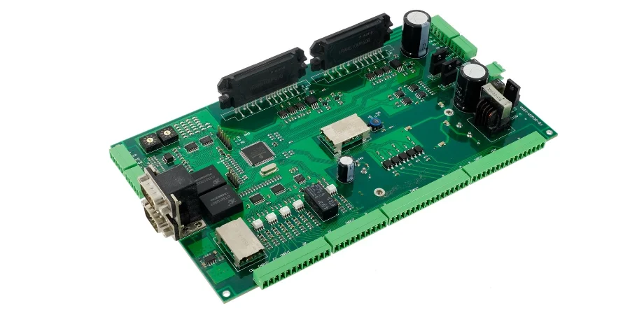
Choose an actuator PCB design by matching motor current, feedback accuracy, thermal limits, and EMC requirements before selecting components or approving manufacturing. Engineers need evidence from the PCB supplier: stackup capability, copper thickness, thermal test data, impedance control documentation, and inspection records. A linear actuator controller typically prioritizes reliable H-bridge switching, position feedback, and protection circuits, while a servo control PCB requires faster sampling, three-phase current control, encoder integrity, and tighter timing performance. The correct design decision depends on voltage range, continuous current, peak current, environmental conditions, and production validation requirements.
What specifications should be defined before designing an actuator PCB?
The first design decision is identifying the actuator operating profile. A PCB that controls a small linear actuator at 12V has very different requirements from a servo drive controlling a three-phase motor at industrial power levels.
Define these parameters before schematic design:
- Motor supply voltage: common actuator systems use 12-48V motor rails.
- Logic voltage: control electronics commonly operate at 3.3-5V.
- Continuous current requirement: actuator PCBs commonly operate from 1-50A depending on thermal design.
- Peak current requirement: short-duration peaks can reach 2-3 times continuous current.
- Feedback type: potentiometer, Hall sensor, optical encoder, quadrature encoder, SPI, SSI, or BiSS.
- Motion accuracy requirement: precision manufacturing applications may require ±5 micrometers positioning repeatability.
- Communication requirements: EtherCAT is used for deterministic synchronized motion, while CAN provides reliable lower-speed communication with strong noise immunity.
The PCB architecture should be selected after these requirements are known because power delivery, layer count, copper weight, thermal design, and EMI control directly affect actuator performance.
How does a linear actuator PCB differ from a servo control PCB?
Linear actuator PCBs usually control a single motor axis with simpler feedback requirements. Servo control PCBs require more advanced timing, current measurement, and feedback processing because they regulate motor position, speed, and torque continuously.
Linear actuator PCB design requirements
A linear actuator controller normally includes:
- H-bridge motor control circuitry.
- Position feedback input.
- Current sensing.
- Limit switch protection.
- Motor voltage switching.
- Logic and analog signal isolation.
For applications requiring 5A or less, integrated motor drivers such as the DRV8871 can provide motor direction and speed control with built-in protection features. Higher-current systems typically require discrete MOSFET arrangements on heavy copper PCB designs to handle thermal dissipation.
Position feedback can use:
- Potentiometric sensors.
- Optical encoders.
- Hall effect sensors.
The PCB must provide stable reference voltages and filtering for sensor signals. Differential routing improves noise immunity when encoder signals travel through longer cables, and controlled impedance routing may be required for high-speed feedback interfaces. Use the impedance calculator to verify trace geometry for differential encoder pairs.
Servo motor control PCB design requirements
Servo systems require additional hardware because they implement closed-loop control with faster response requirements.
Typical servo PCB elements include:
- Motor control ICs such as the TMC4671.
- ARM Cortex-M microcontrollers.
- Field-oriented control (FOC) firmware support.
- High-speed ADC sampling.
- Precise PWM generation.
- Three-phase current sensing.
- Encoder interfaces.
Three-phase servo motors require current measurement on at least two phases. Inline shunt resistors with differential amplifiers provide a cost-effective approach, while isolated current sensors improve noise immunity in higher-power systems.
Encoder interfaces may include:
- Quadrature signals with differential receivers and termination.
- Absolute encoders using SPI, SSI, or BiSS protocols.
Gate driver layouts must minimize gate drive loop inductance while maintaining isolation between power and control sections. IGBT and MOSFET gate drivers commonly use bootstrap circuits for switching control.
Which actuator PCB material and thermal design should be selected?
Thermal management determines whether an actuator PCB can maintain control accuracy during continuous operation. Heat sources include:
- Power MOSFET switching losses.
- Current sensing resistors.
- Voltage regulators.
- Gate driver circuits.
For standard dielectric materials, thermal conductivity is typically around 1.5-3 W/mK. High-performance thermal PCB materials are commonly available in approximately 4-8 W/mK ranges for applications requiring improved heat transfer.
Thermal vias create vertical heat paths between surface components and internal copper planes. Typical thermal via diameters are commonly in the 200-400 µm range depending on manufacturing capability.
Component placement should separate heat-generating components from temperature-sensitive circuits. Power components should be positioned near PCB edges when external heat sink mounting is required. Temperature sensors should be located away from direct heat sources to avoid inaccurate readings.
External heat sinks generally become necessary for actuator PCB power dissipation above 15W. Forced-air cooling can increase thermal capacity, while thermal interface materials improve heat transfer between components and cooling structures.
What actuator PCB parameters create the highest design risk?
The following decision table connects design parameters with failure risks and required evidence from manufacturing partners.
| Parameter | Typical design values | Failure risk | Evidence to request |
|---|---|---|---|
| Motor voltage rail | 12-48V common actuator range | Insufficient isolation or power distribution failure | PCB stackup, electrical spacing documentation |
| Continuous current | 1-50A depending on design | Excessive copper heating and voltage drop | Thermal test report, copper weight confirmation |
| Peak current | 2-3 times continuous current for short periods | MOSFET stress and protection failure | Protection circuit validation data |
| Linear actuator driver | DRV8871 for applications up to 5A, discrete MOSFET designs for higher current | Driver overheating or switching loss | Schematic review and thermal analysis |
| High-power PCB copper | Heavy copper construction for higher current designs | Trace overheating | Copper thickness measurement |
| Thermal conductivity | Standard dielectric approximately 1.5-3 W/mK; high-performance materials approximately 4-8 W/mK | Heat accumulation and control drift | Material certificate and thermal test data |
| Motor feedback | Potentiometer, Hall sensor, optical encoder, quadrature, SPI, SSI, BiSS | Position errors caused by noise | Signal integrity test results |
| Precision positioning | CNC applications may require ±5 micrometers | Thermal drift and unstable references | Environmental test records |
| Servo timing | Fast ADC sampling and precise PWM generation | Control instability | Firmware timing documentation |
How should engineers select actuator PCB components by current rating?
Actuator PCB component selection is driven primarily by continuous motor current. The guide below maps current range to the recommended driver topology, copper weight, sense-resistor approach, thermal management, and the supplier evidence that should be required before approving the design.
|| Current range | Recommended driver | Copper weight | Sense resistor approach | Thermal management | Key evidence | |---|---|---|---|---|---| | 1–5 A | Integrated driver (e.g. DRV8871) | 1 oz | Inline shunt + differential amplifier | Standard FR-4 | Thermal test, current calibration data | | 5–20 A | Discrete MOSFET | 2 oz | Inline shunt + differential amplifier | Thermal vias | Thermal test, copper weight verification | | 20–50 A | Discrete MOSFET + gate driver | 3–4 oz | Isolated current sensor | High-Tg FR-4 + heatsink | Thermal test, copper weight verification, current calibration data | | 50 A+ | IGBT | 6+ oz heavy copper | Hall effect current sensor | Active cooling (forced air or liquid) | Thermal test, copper weight verification, current calibration data |
Engineers should use this guide to align the driver topology, copper weight, and sensing method with the motor current before finalizing the schematic. A design that pairs a 30 A motor with 1 oz copper and an inline shunt will fail thermal validation and produce inaccurate current feedback.
How should actuator PCB layout prevent EMI and signal failures?
Actuator systems combine high-current switching with sensitive feedback signals, creating a high risk of electromagnetic interference.
Recommended PCB layout practices include:
Separate power and control regions
Motor switching circuits should be physically separated from analog feedback and communication interfaces. High-current paths should use short return paths to reduce switching loop area.
Control impedance on sensitive signals
Differential encoder signals require controlled routing when signal integrity is critical. Impedance control should be verified through PCB fabrication documentation.
Minimize gate driver loops
MOSFET and IGBT gate drive traces should be short and compact. Excessive loop area increases parasitic inductance and can create switching noise.
Protect feedback circuits
Encoder and sensor inputs should include:
- Filtering components.
- Proper grounding.
- Shielding where required.
- Stable reference voltage generation.
How should actuator PCB testing be specified before production?
A reliable actuator PCB requires validation beyond basic electrical inspection.
Testing should include:
Electrical validation
Verify:
- Power supply operation across load and line voltage ranges.
- Current limiting behavior.
- Thermal shutdown operation.
- Signal integrity.
- PWM timing performance.
Functional load testing
Operate the actuator under mechanical load while measuring:
- Current consumption.
- Temperature rise.
- Position accuracy.
- Control stability.
EMC and environmental testing
Industrial actuator systems may require:
- Conducted emissions testing.
- Temperature cycling.
- Vibration testing.
Temperature cycling validates solder joint reliability across industrial operating ranges. Vibration testing verifies mechanical robustness in demanding environments.
Which PCB manufacturing options are suitable for actuator control boards?
Selection depends on current, thermal load, signal speed, and reliability requirements.
Multilayer PCB construction
Multilayer PCB designs provide dedicated power planes, improved signal isolation, and better noise control.
For actuator systems, multilayer construction supports:
- Separate motor and logic sections.
- Controlled impedance routing.
- Improved power distribution.
Heavy copper PCB construction
Heavy copper PCB designs are suitable for higher-current motor paths where standard copper thickness cannot handle thermal requirements.
High thermal conductivity PCB materials
High thermal conductivity PCB options improve heat transfer for power-intensive actuator applications.
SMT assembly
Complex actuator control boards require accurate component placement and repeatable manufacturing processes. Our SMT assembly capabilities support reliable production of motor control assemblies with inspection and quality processes.
What files and specifications should be included in an actuator PCB RFQ?
A complete RFQ package reduces manufacturing assumptions and improves supplier comparison.
Submit these files:
- Gerber files.
- BOM with manufacturer part numbers.
- PCB assembly drawings.
- Schematic files.
- PCB layout source files when available.
- Stackup requirements.
- Via drawing.
- Drill files.
- Pick-and-place files.
- Fabrication notes.
- Controlled impedance requirements.
- Copper weight requirements.
- Surface finish requirements.
- Assembly instructions.
Request these supplier documents:
- PCB stackup confirmation.
- Cross-section report.
- Copper thickness verification.
- Material specifications.
- Thermal test report for high-current designs.
- Impedance test report when controlled impedance is required.
- AOI and inspection records.
- Functional test plan.
- Environmental test documentation where applicable.
A supplier response should demonstrate that the PCB manufacturing process matches the electrical and thermal requirements of the actuator system.
What applications require different actuator PCB decisions?
Precision manufacturing
CNC machines and precision motion systems require stable references, thermal control, and strong EMI immunity. Position accuracy requirements can reach ±5 micrometers, making thermal drift and signal noise major design considerations.
Packaging equipment
High-speed packaging machines require rapid acceleration, deceleration, and accurate positioning. Multi-axis systems require deterministic communication and synchronized control.
Medical and laboratory equipment
Medical and laboratory motion systems prioritize low noise operation, precision control, and documentation requirements. PCB designs must minimize electromagnetic emissions and support reliability validation.
Industrial safety systems
Safety-rated actuator systems may require redundant monitoring, fail-safe operation, and communication with safety PLC systems.
Frequently Asked Questions
Q: What is the main difference between a linear actuator PCB and a servo control PCB?
Linear actuator PCBs usually control single-axis movement with simpler feedback systems. Servo control PCBs manage multi-phase motors using advanced current control, encoder feedback, and higher-speed processing.
Q: How can actuator PCB designers reduce thermal drift?
Use thermal monitoring, temperature-compensated components, appropriate PCB materials, and software compensation where required. Thermal design should prevent heat sources from affecting sensitive measurement circuits.
Q: Which communication protocols are common for multi-axis actuator systems?
EtherCAT provides deterministic real-time synchronization for motion systems. CAN provides reliable communication for lower-speed industrial networks.
Q: How important is EMI control in actuator PCB design?
EMI control is critical because motor switching noise can interfere with feedback and communication signals. Grounding, filtering, layout separation, and shielding strategies should be considered during PCB design.
Q: What current levels can actuator PCBs support?
Most actuator control PCBs operate from 1-50A continuous current depending on thermal design. Peak currents can reach 2-3 times continuous current for short durations.
For actuator PCB manufacturing decisions, provide complete design files and request measurable production evidence before approving a supplier.